Tool for minimally invasive surgery and method for using the same

a technology for surgery and surgery, applied in the field of easy-to-control tools for minimally invasive surgery, can solve the problems of difficulty in performing the dexterous handling required for surgery, no suitable tool for supporting the idea, and conventional minimally invasive surgical tools cannot even approach, so as to achieve easy access to the area, simple drive control elements, and minimal

Inactive Publication Date: 2011-07-14
JEONG CHANG WOOK
View PDF14 Cites 212 Cited by
  • Summary
  • Abstract
  • Description
  • Claims
  • Application Information

AI Technical Summary

Benefits of technology

Another object of the present invention is to provide a tool for minimally invasive surgery, which has an end effector of high-degree-of-freedom motion.
Still another object of the present invention is to provide a tool for minimally invasive surgery, which operates in a dexterous manner with relatively simple drive control elements.
Still another object of the present invention is to provide a tool for minimally invasive surgery, which easily accesses to areas that are hidden by specific organs, including plural joint portions, for surgery.
Still another object of the present invention is to provide a surgical tool for achieving a minimally invasive surgery in a dexterous and convenient manner with the least number of incisions in a patient's body, most preferably, with only one incision.

Problems solved by technology

Particularly, since the traditional end effector has no bending portion like a joint, it is difficult to perform a dexterous handling required for surgery.
Moreover, when a surgical site is located behind a specific organ, the conventional minimally invasive surgical tools cannot even approach there.
An attempt to solve such a problem has been made by proposing the idea of forming only one incision and then inserting a trocar into the incision for surgery, but unfortunately there is no suitable tool for supporting the idea.

Method used


Image

  • Tool for minimally invasive surgery and method for using the same
  • Tool for minimally invasive surgery and method for using the same
  • Tool for minimally invasive surgery and method for using the same

Examples


embodiment 1

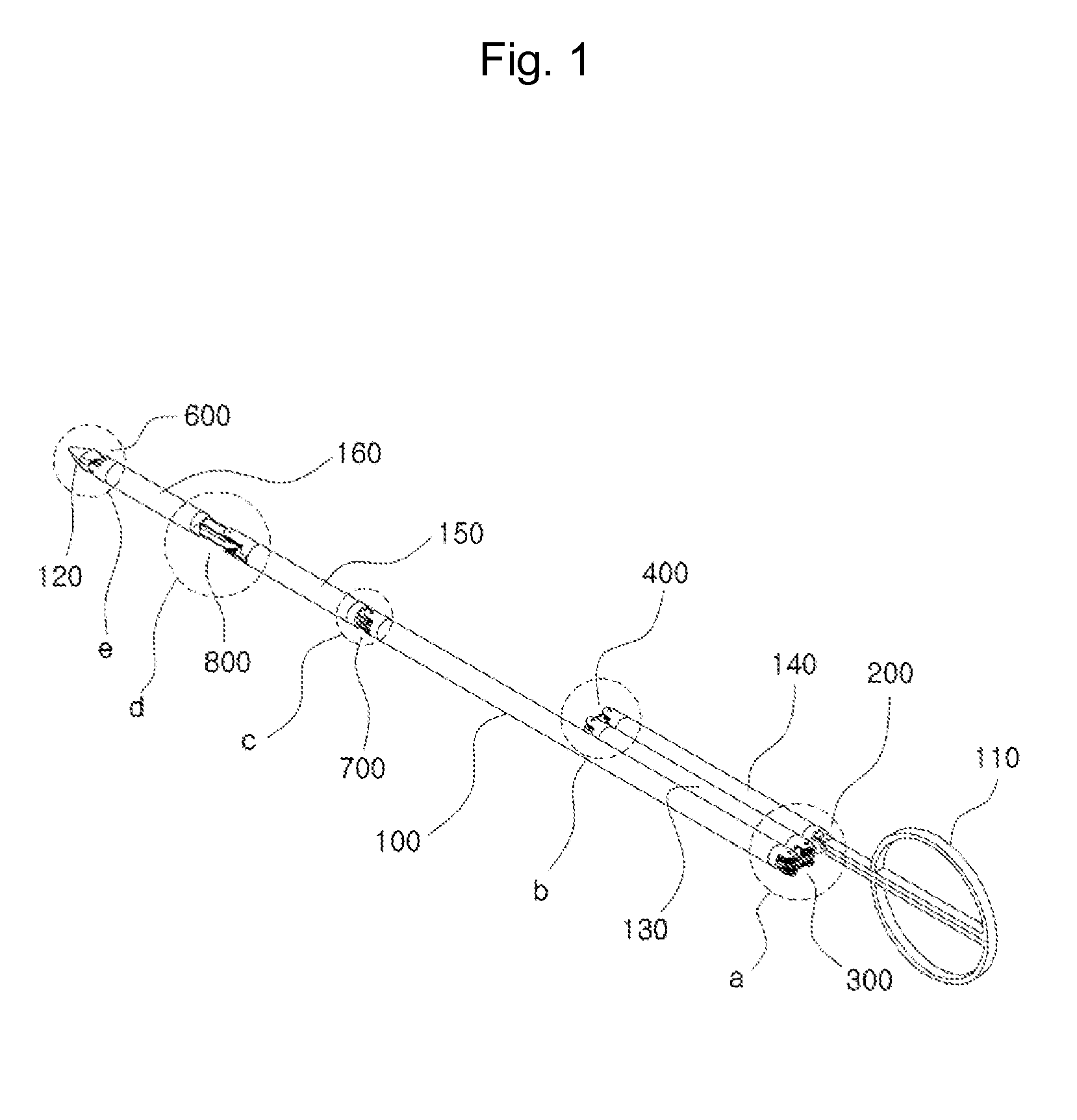
FIG. 1 is a perspective view showing the outer appearance of a tool 1 for minimally invasive surgery, in accordance with a first embodiment of the present invention.

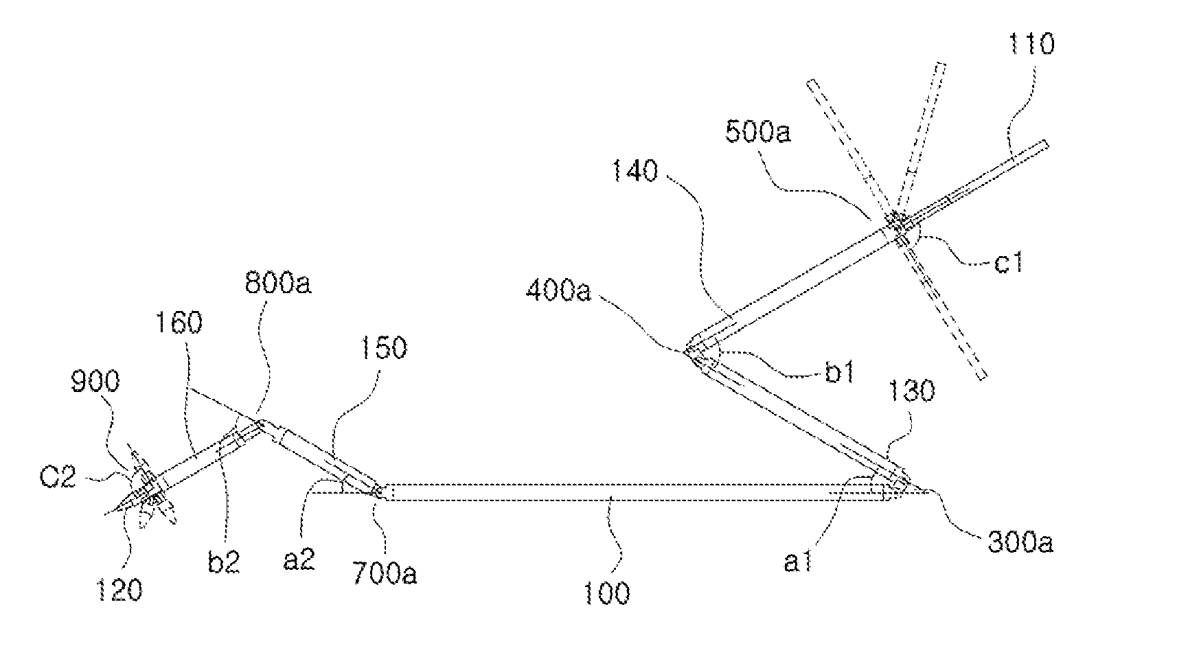
Referring to FIG. 1, the tool 1 for minimally invasive surgery of this embodiment includes a shaft 100 (i.e., main shaft), an adjustment handle 110, an end effector 120, first and second control shafts 130 and 140, first and second actuating shafts 150 and 160, a pitch control part 200, first and second yaw control parts 300 and 400, a pitch actuating part 600, and first and second yaw actuating parts 700 and 800.

First, as shown in FIG. 1, there is the main shaft 100, and the first and second control shafts 130 and 140 are positioned in sequence from one end of the main shaft 100, and the first and the second actuating shafts 150 and 160 are positioned in sequence from the other end of the main shaft 100. At least part of the shafts have, if necessary, one or plural spaces (for example, tube-shape, lotus root-shape or sp...

embodiment 2

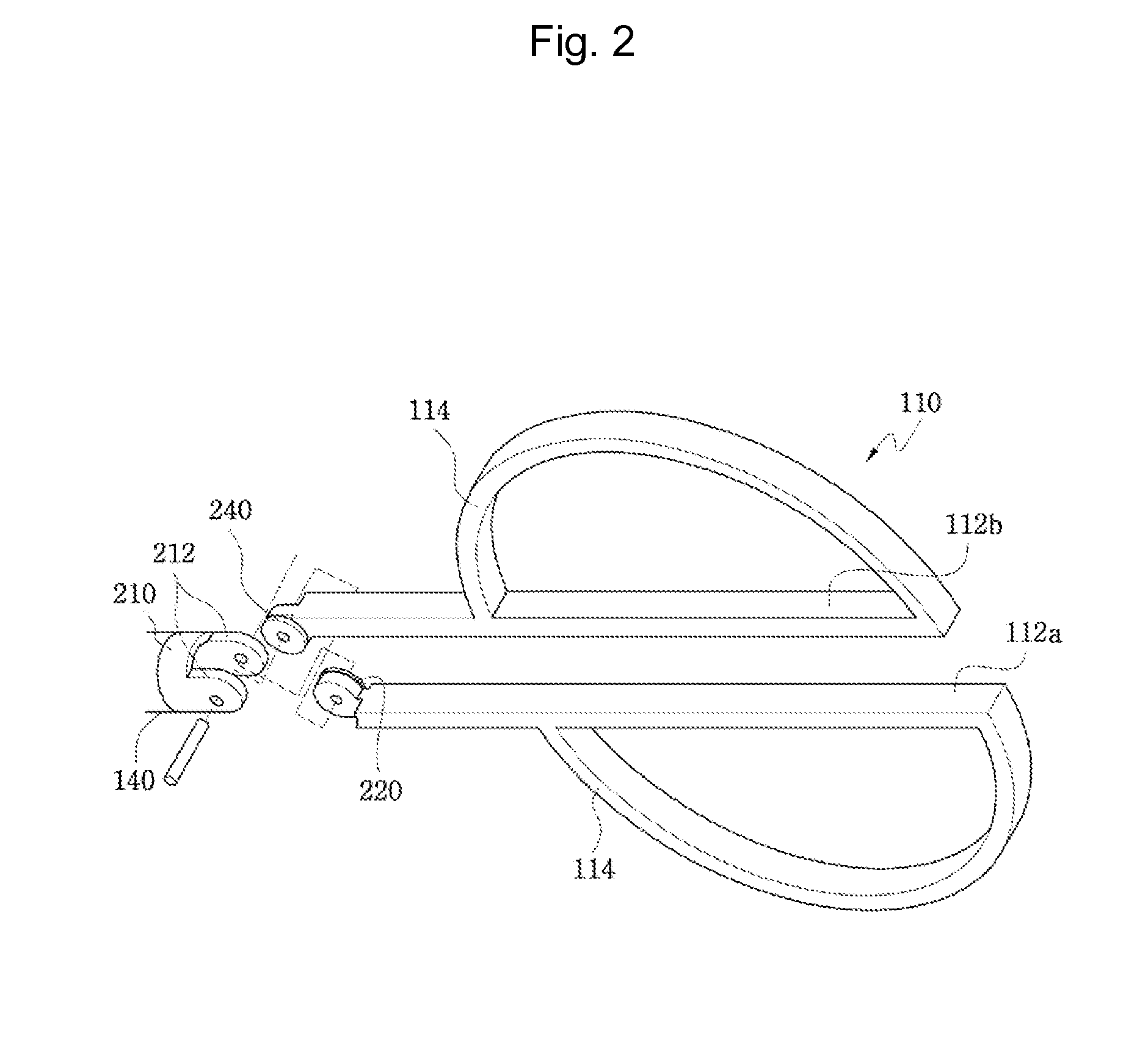
FIG. 24 is a perspective view showing a connection between an adjustment handle 110 and a second control shaft 140 of a tool for minimally invasive surgery in accordance with a second embodiment of the present invention. In accordance with the second embodiment of the present invention, the adjustment handle 110 is connected to the second control shaft 140 by means of a pitch control part 200a.

More details on such a configuration will be given below.

The pitch control part 200a can include a first pitch cable pulley 220a, a second pitch cable pulley 240a, and a third pitch cable pulley 260a. As shown in the drawing, out of first and second rods 112a and 112b that constitute the adjustment handle 110, the first rod 112a has the first pitch cable pulley 220a fixed to its extended end and the second pitch cable pulley 240a positioned on the same rotation axis to rotate independently inside a connection end 212 that is formed on a connection ring 210 at the end of the second control sha...

embodiment 3

FIG. 26 is a perspective view showing the outer appearance of a tool for minimally invasive surgery in accordance with a third embodiment of the present invention, FIG. 27 is a detailed view of ‘b’ portion in FIG. 26, and FIG. 28 is a detailed view of ‘a’ portion in FIG. 26.

In accordance with the third embodiment of the present invention, an adjustment handle 110a for controlling an operation of an end effector 120a in a hook electrode form is connected to a second control shaft 140 by means of a pitch control part 200, and the end effector 120a is connected to a second actuating shaft 160 by means of a pitch actuating part 600.

In this embodiment, first and second pitch cables PC1 and PC2 operate together to transfer a motion of the adjustment handle 110a in a pitch / yaw direction to the end effector 120a.

In addition, unlike in the first embodiment, the end effector 120a of this embodiment has a bar shape with bendable portions (or any other shape, e.g., a ring shape, depending on u...


PUM


Abstract

The present invention relates to an easy-to-control tool for minimally invasive surgery and a method for using the same. In accordance with an aspect of the present invention, there is provided a tool for minimally invasive surgery and a method for using the same comprising, a main shaft, a first control shaft and a second control shaft positioned in sequence from one end of the main shaft, a first actuating shaft and a second actuating shaft positioned in sequence from the other end of the main shaft, an adjustment handle positioned around one end of the second control shaft, an end effector positioned around one end of the second actuating shaft, a pitch control part positioned around one position of the positions between the main shaft and the first control shaft, between the first control shaft and the second control shaft, and between the second control shaft and the adjustment handle, for transferring a motion of the adjustment handle in a pitch direction to the end effector, a first yaw control part and a second yaw control part positioned around the other positions of the positions between the main shaft and the first control shaft, between the first control shaft and the second control shaft, and between the second control shaft and the adjustment handle, respectively, for transferring a motion of the adjustment handle in a yaw direction to the end effector, a pitch actuating part positioned around one position of the positions between the main shaft and the first actuating shaft, between the first actuating shaft and the second actuating shaft, and between the second actuating shaft and the end effector, a first yaw actuating part and a second yaw actuating part positioned around the other positions of the positions between the main shaft and the first actuating shaft, between the first actuating shaft and the second actuating shaft, and between the second actuating shaft and the end effector, respectively, a first pitch cable and a second pitch cable for transferring motions from the pitch control part, the first yaw control part, and the second yaw control part to the pitch actuating part, the first yaw actuating part, and the second yaw actuating part, respectively, and a yaw cable for transferring a motion from the first yaw control part to the first yaw actuating part with the first pitch cable and the second pitch cable.

Description

FIELD OF THE INVENTIONThe present invention relates to an easy-to-control tool for minimally invasive surgery and a method for using the same, and more specifically, to a tool for minimally invasive surgery, which performs minimally invasive surgery in a dexterous and convenient manner by actuating an end effector through the control of an adjustment handle, and a method for using the same.BACKGROUND OF THE INVENTIONMinimally invasive surgery is a surgical approach that involves use of instruments inserted through several tiny incision openings to perform a surgery causing minimal tissue trauma.This minimally invasive surgery relatively reduces changes in metabolism of the patient in the period of post-surgical care, so it is beneficial to rapid recovery of the patient. Therefore, using such minimally invasive surgery shortens length of a hospital stay of the patient after the surgery and allows patients to return to normal physical activities more quickly. In addition, minimally in...

Claims


Application Information

Patent Timeline
Patent Type & Authority Applications(United States)
IPC IPC(8): A61B17/00
CPCA61B17/29A61B19/22A61B2017/00398A61B2017/2901A61B19/2203A61B2017/2908A61B2017/291A61B2017/2927A61B2019/2242A61B2017/2905A61B34/30A61B34/70A61B34/71A61B17/00A61B17/28A61B17/32A61B17/34
Inventor JEONG, CHANG WOOK
Owner JEONG CHANG WOOK
Why Eureka
Try Eureka