Supercharge Your Innovation With Domain-Expert AI Agents!

Adaptive Gas Turbine Vane Separator System and Method

a technology of gas turbine and separator, which is applied in the field of turbine engines, can solve the problems of undesirable reduction in air flow, corrosion and/or other damage to the turbine engine, etc., and achieve the effect of facilitating the reduction of moisture entering

Inactive Publication Date: 2011-07-21
BHA ALTAIR
View PDF11 Cites 2 Cited by
  • Summary
  • Abstract
  • Description
  • Claims
  • Application Information

AI Technical Summary

Benefits of technology

"The patent describes a system for reducing moisture entering a turbine engine by using a vane separator system. This system includes a slide rail and a plurality of rotating vanes that are moved by a drive motor to selectively reduce the amount of moisture entering through the air inlet. The technical effect of this system is to improve the efficiency and reliability of turbine engines by preventing damage caused by moisture and other contaminants in the air."

Problems solved by technology

Within at least some known turbine engines, continued exposure to incoming precipitation and / or other moisture may eventually produce corrosion and / or other damage to the turbine engine.
Although such systems generally remove moisture from the air entering the air inlet, known vane separator systems may reduce air flow to the turbine engine.
Furthermore, there are at least some environmental conditions during which the vane separators are not required and any reduction in air flow is undesirable.

Method used


Image

  • Adaptive Gas Turbine Vane Separator System and Method
  • Adaptive Gas Turbine Vane Separator System and Method
  • Adaptive Gas Turbine Vane Separator System and Method

Examples


Embodiment Construction

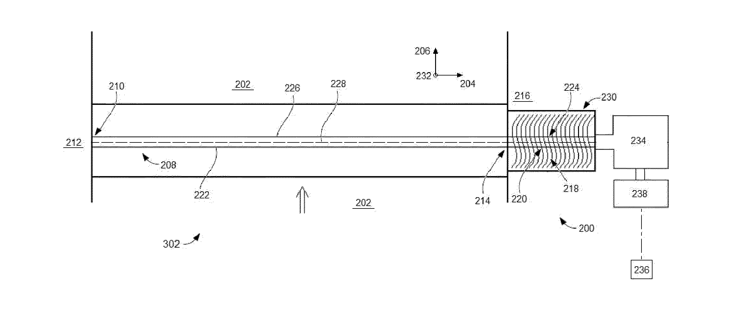
[0009]The methods and systems described herein include a gas turbine engine including an adaptive gas turbine vane separator system. The vane separator system is selectively actuatable to reduce an amount of precipitation and / or other moisture from entering a gas turbine engine. Additionally, the vane separator system is selectively retractable to reduce a pressure loss of the gas turbine engine.

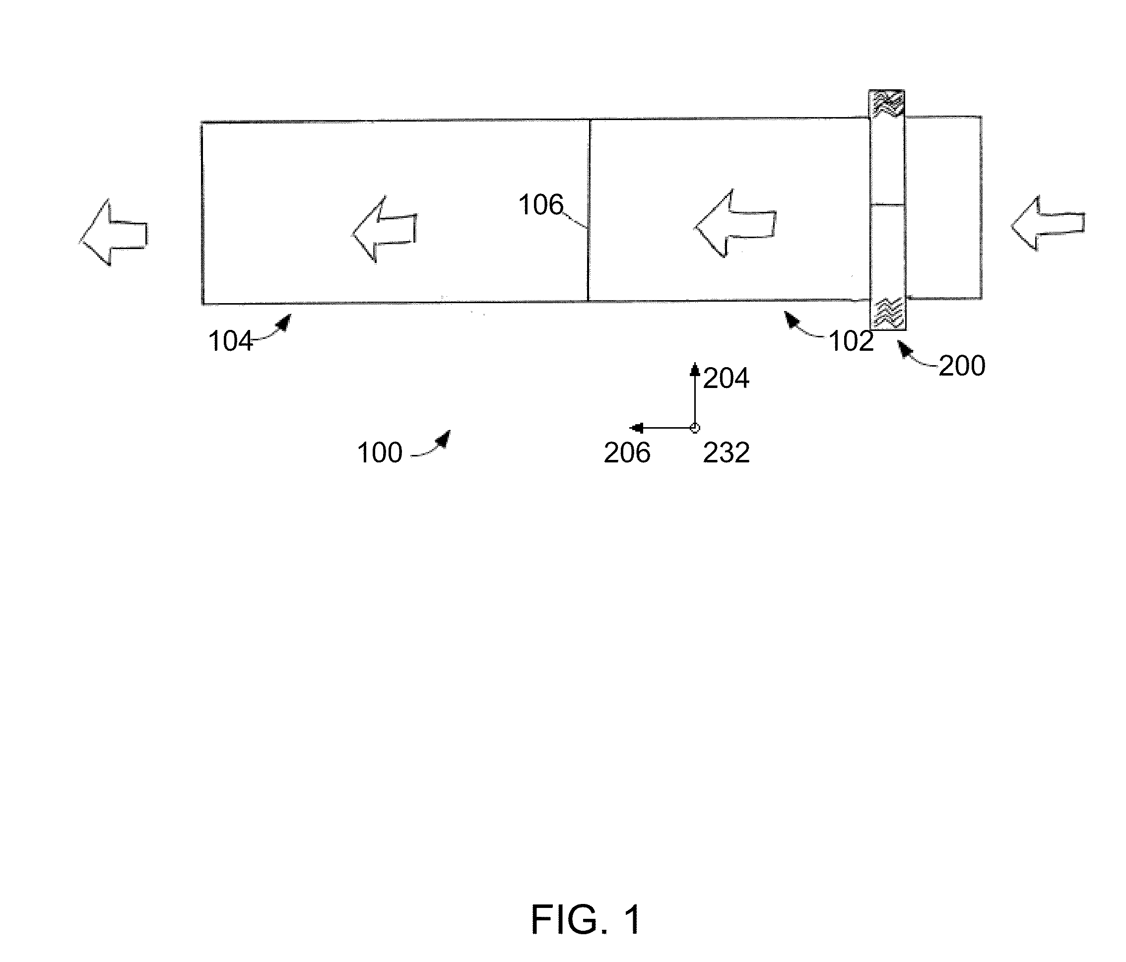
[0010]FIG. 1 is a schematic illustration of an exemplary gas turbine engine system 100 that includes an inlet filter house 102 and a gas turbine engine 104. In the exemplary embodiment, inlet filter house 102 includes a vane separator system 200, described in further detail below. In the exemplary embodiment, vane separator system 200 is oriented such that vane separator system 200 is substantially perpendicular to air duct 202. More specifically, in the exemplary embodiment, vane separator system 200 has a longitudinal axis that extends generally along an X-axis 204, and air duct 202 has a ...


PUM


Abstract

An adaptive vane separator system is provided for use with an inlet filter house of a gas turbine engine system. The vane separator system is coupled to the inlet filter house. The vane separator system includes a slide rail and a plurality of vanes rotatably coupled to the slide rail. The inlet filter house is configured to channel air to an air inlet of a turbine engine. A drive motor is coupled to the vane separator system. The drive motor is operable to selectively move at least one of the vanes to facilitate reducing an amount of moisture channeled through the air inlet.

Description

BACKGROUND OF THE INVENTION[0001]The subject matter disclosed herein relates generally to turbine engines and, more particularly, to a vane separator system for use with a turbine engine.[0002]At least some known turbine engines include an air inlet, a core engine, and an exhaust flue. Within at least some known turbine engines, continued exposure to incoming precipitation and / or other moisture may eventually produce corrosion and / or other damage to the turbine engine. To prevent precipitation and / or other moisture from entering the turbine engine, at least some known turbine engines include a vane separator system that separates the particles, precipitation, and / or other moisture from the air entering the air inlet. Although such systems generally remove moisture from the air entering the air inlet, known vane separator systems may reduce air flow to the turbine engine. Performance and / or operating efficiency of the turbine engine may decrease depending on the severity of the reduc...

Claims


Application Information

Patent Timeline
Patent Type & Authority Applications(United States)
IPC IPC(8): F02C7/04
CPCF02C7/055F02C7/052
Inventor JARRIER, ETIENNE RENELARCOMBE, SIMON
Owner BHA ALTAIR
Features
  • R&D
  • Intellectual Property
  • Life Sciences
  • Materials
  • Tech Scout
  • Unparalleled Data Quality
  • Higher Quality Content
  • 60% Fewer Hallucinations
Learn More