Pump suction gas separator

a gas separator and pump technology, applied in the direction of liquid degasification, separation processes, manufacturing tools, etc., can solve the problems of inoperable pumps and systems, inability to perform safety functions, and inability to operate and maintain pumps and systems, etc., to achieve the effect of promoting flow stratification

Inactive Publication Date: 2011-07-21
WESTINGHOUSE ELECTRIC CORP
View PDF5 Cites 13 Cited by
  • Summary
  • Abstract
  • Description
  • Claims
  • Application Information

AI Technical Summary

Benefits of technology

[0008]The disclosed concept provides for a gas separator on pipe structured to transport a liquid. The gas separator includes a section of piping, located upstream of the pump, having an increased diameter which is in fluid communication with an overhead pocket. Fluid flow in the portion of the pipe having an increased diameter is at a slower rate than other portions of the pipe. The slower fluid speed allows for entrained gasses to stratify and float to the top of the pipe whereupon the gas will flow into the pocket. Thus, the fluid downstream from the gas separator has a reduced amount of gas in the liquid flow.
[0009]More specifically, the gas separator includes a section of horizontal piping upstream of the pump that is replaced with larger diameter piping. This is accomplished by removing a section of pipe and installing an expander, a length of larger-diameter pipe, and a reducer to return to the diameter of the pump inlet nozzle. The purpose of the larger pipe diameter is to reduce the fluid velocity to a level where any entrained gas will stratify under the effects of buoyancy to the top of the pipe. Generally, the speed of the fluid is reduced to about five feet per second.
[0015]The device is totally passive and relies on no power operated equipment or actuation signals. This improves the reliability of the invention.
[0018]The device is made of simple off-the-shelf components. This facilitates fabrication of the device.

Problems solved by technology

Gas intrusion in ECCS, DHR and CSS piping systems has been an ongoing issue at power plants.
These events have rendered pumps and systems inoperable and incapable of performing their safety functions.
These current approaches do not work if the gas collects at a location that is not monitored by UM or at a location at which a vent valve does not exist.

Method used


Image

  • Pump suction gas separator
  • Pump suction gas separator
  • Pump suction gas separator

Examples


Embodiment Construction

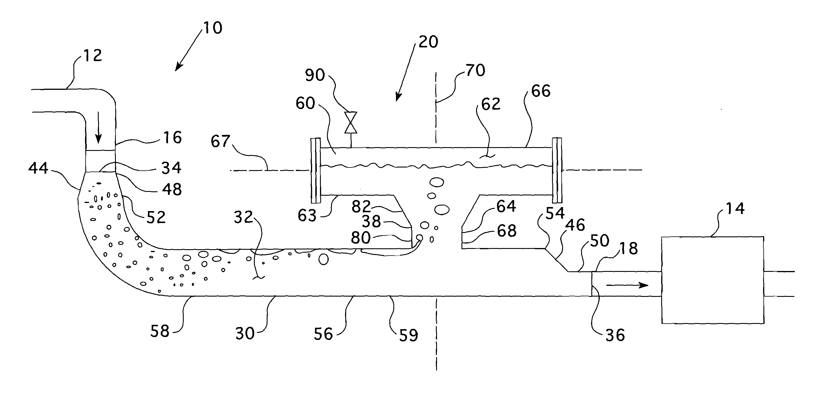
[0027]As is known, pipes generally have a circular cross-sectional area. The following discussion shall assume a pipe having a circular cross-sectional area but the disclosed concept is not so limited. Accordingly, any words used herein that relate to a pipe having a circular cross-sectional shall be interpreted broadly so as to include pipes with other cross-sectional shapes. For example, a “radius” shall be interpreted broadly to include the major and minor radii of a pipe having an elliptical cross-sectional area as well as the length, width, or diagonal of a square / rectangular pipe.

[0028]As used herein, “coupled” means a link between two or more elements, whether direct or indirect, so long as a link occurs.

[0029]As used herein, “directly coupled” means that two elements are directly in contact with each other.

[0030]As used herein, “fixedly coupled” or “fixed” means that two components are coupled so as to move as one while maintaining a constant orientation relative to each oth...


PUM

PropertyMeasurementUnit
speedaaaaaaaaaa
speedaaaaaaaaaa
radiusaaaaaaaaaa

Abstract

A gas separator on pipe structured to transport a liquid is provided. The gas separator includes a section of piping, located upstream of a pump, having an increased diameter which is in fluid communication with an overhead pocket. Fluid flow in the portion of the pipe having an increased diameter is at a slower rate than other portions of the pipe. The slower fluid speed allows entrained gasses to stratify and float to the top of the pipe whereupon the gas will flow into the pocket. Thus, the fluid downstream from the gas separator has a reduced amount of gas in the liquid flow.

Description

CROSS REFERENCE TO RELATED APPLICATIONS[0001]This application is related to and claims priority from provisional application Ser. No. 61 / 295,191, filed Jan. 15, 2010, entitled PUMP SUCTION GAS SEPARATOR and Ser. No. 61 / 296,503, filed Jan. 20, 2010, entitled PUMP SUCTION GAS SEPARATOR.BACKGROUND OF THE INVENTION[0002]1. Field of the Invention[0003]This device is installed in the suction of a pump and removes any entrained gases from the liquid without significant additional pressure losses. This device is intended to be used in the suction of safety related emergency core cooling system (ECCS), decay heat removal (DHR) and containment spray system (CSS) pumps in light water reactors.[0004]This device is fully effective in removing during dynamic post-accident events and ensures the pump remains fully functional to perform its post accident conditions. This is the novel feature of this device. All currently known gas removal systems rely on venting the gas prior to the post accident e...

Claims


Application Information

Patent Timeline
Patent Type & Authority Applications(United States)
IPC IPC(8): B01D19/00B23P11/00
CPCY10T29/49826B01D19/0042
Inventor SWANTNER, STEPHENSWARTZ, MATTHEW
Owner WESTINGHOUSE ELECTRIC CORP
Why Eureka
Try Eureka