Combined tramp rod and Anti-roll bar

a combination of tramp rod and anti-roll bar technology, applied in the direction of interconnection system, resilient suspension, vehicle spring, etc., can solve the problems of affecting the steering performance and/or vehicle stability, affecting the stability of the vehicle, and the centre section being subject to a combination of torsion and bending loads

Inactive Publication Date: 2011-07-21
FORD GLOBAL TECH LLC
View PDF15 Cites 13 Cited by
  • Summary
  • Abstract
  • Description
  • Claims
  • Application Information

AI Technical Summary

Benefits of technology

[0019]The combined anti-roll bar and tramp rod may be provided with D-blocks or bushings that secure the bar to an axle beam and may also provide compliance understeer resulting in the outside tire steering into the cornering radius (toe-in).
[0020]With the anti-roll bar installation described below,

Problems solved by technology

Too much roll is undesirable because it places difficulties for the driver to make accurate observations on the road conditions and the motion of the vehicle.
Excessive roll may also interfere with steering performance and/or the stability of the vehicle.
Due to package constraints the centre section will sometimes be subjected to a combination of torsion and bending loads.
However, leaf spring suspensions suffer from the inherent disadvantage of relatively low wind-up stiffness, i.e. angular articulation of the axle (in side view) under driving/braking forces.
This articulation is undesirable, because it deteriorates road holding and traction through uncontrolled axle motion.
Further, it has adverse NVH (noise, vibration and harshness) effects and poses additional stress on the driveshaft, which in extreme cases may lead to axle break

Method used


Image

  • Combined tramp rod and Anti-roll bar
  • Combined tramp rod and Anti-roll bar
  • Combined tramp rod and Anti-roll bar

Examples


Embodiment Construction

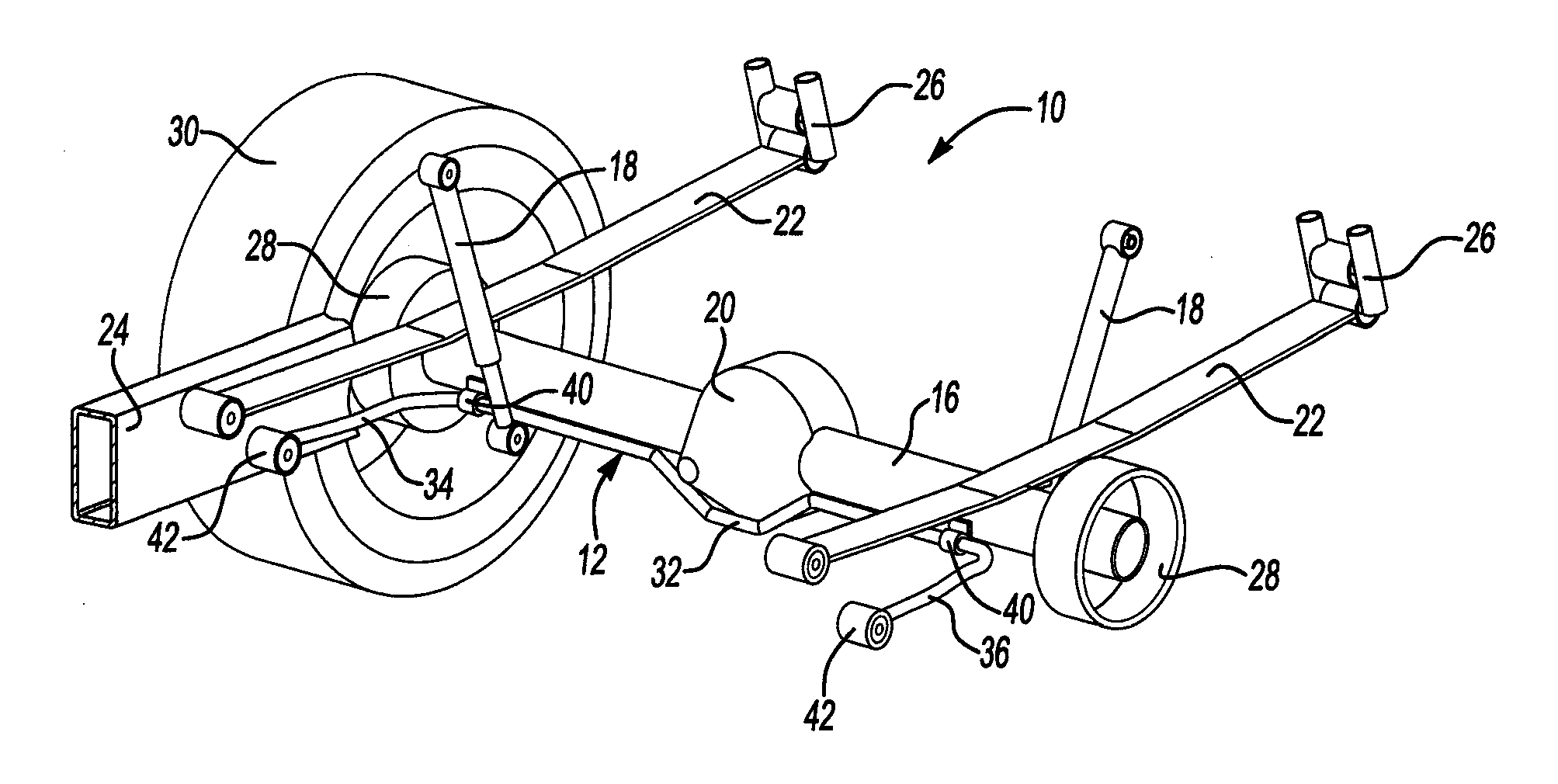
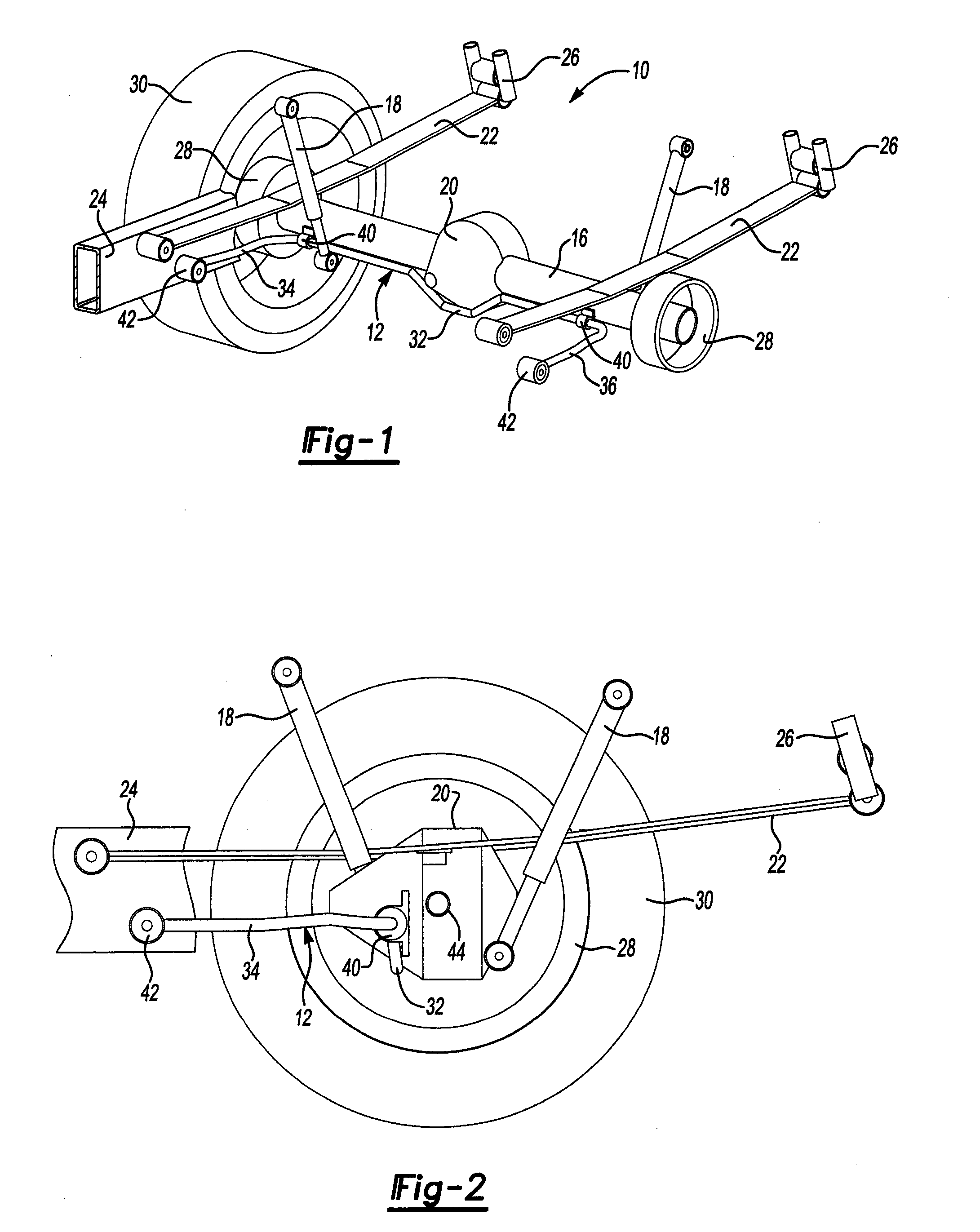
[0028]Referring to FIG. 1, a rear suspension system generally indicated by reference numeral 10 is shown with the vehicle and several component parts not being illustrated to provide better visibility of the components of the suspension system 10 that are material to the illustrated combined tramp rod and anti-roll bar 12.

[0029]The tramp rod and anti-roll bar 12 is assembled to a rear axle beam 16. Dampers 18, or shock absorbers, are secured between the rear axle beam 16 and the body of the vehicle (not shown). A differential 20 is provided on the axle beam 16. Torque is delivered through a driveshaft (not shown) to the differential 20. Leaf springs 22 are provided on opposite sides of the rear suspension system 10. The rear axle beam 16 in FIG. 1 is shown in an overslung arrangement wherein the rear axle 16 is below the leaf springs 22. A frame rail 24 is partially shown in FIG. 1. It should be understood that the frame rail 24 is part of the vehicle chassis that is not otherwise s...


PUM


Abstract

A combined tramp rod and anti-roll bar is secured between a rear axle beam and the chassis of a vehicle. The tramp rod and anti-roll bar has an intermediate portion, a right arm and a left arm that are connected by bushings to either the rear axle beam or the frame of the vehicle. The combined tramp rod and anti-roll bar provides roll stiffness control and also resists wind-up of the rear axle when high torque loads are applied to the rear axle. D-bushings that resist sliding movement of the intermediate portion in combination with the splayed arms provide improved compliance understeer performance when lateral loads are applied to the rear suspension.

Description

BACKGROUND[0001]1. Technical Field[0002]The present invention relates to mechanical linkages for reducing lateral roll and axle beam rotation.[0003]2. Background Art[0004]Suspension systems function to isolate the sprung mass of the vehicle from the unsprung masses comprising wheel and axle assemblies. Shock loading and vibration are reduced by springs and dampers. Mechanical linkages may be provided to improve the stability, steering and general handling performance of the vehicle.[0005]Anti-roll bars, or stabiliser bars, are used to reduce the tendency of the vehicle body to roll or rotate about a longitudinal axis in a turn. During cornering, a typical passenger car may roll from 3-8° per g toward the outside of the turn. Too much roll is undesirable because it places difficulties for the driver to make accurate observations on the road conditions and the motion of the vehicle. Excessive roll may also interfere with steering performance and / or the stability of the vehicle.[0006]A...

Claims


Application Information

Patent Timeline
IPC IPC(8): B60G21/05
CPCB60G9/003B60G11/04B60G2204/122B60G2200/31B60G2202/112B60G21/051
Inventor OHRA-AHO, LAURI MIKAELJOHNSON, SIMONREILLY, MATTHEW J.
Owner FORD GLOBAL TECH LLC
Why Eureka
Try Eureka