Apparatus for transferring and loading a reticle with a robotic reticle end-effector

a robotic reticle and end-effector technology, applied in the field of lithography systems, can solve the problems of difficult to align the reticle at the off-line, and difficult to maintain so as to achieve the effect of maintaining the rigidity of the reticle in the plan

Inactive Publication Date: 2006-02-28
ASML HLDG NV
View PDF10 Cites 3 Cited by
  • Summary
  • Abstract
  • Description
  • Claims
  • Application Information

AI Technical Summary

Benefits of technology

[0012]The present invention is an apparatus and method of transferring and loading a reticle onto a receiving station (for example, a reticle exposure stage). More specifically, the present invention is an apparatus and method for providing out-of-plane pre-alignment compliance with the alignment of the reticle at the reticle exposure stage, while maintaining in-plane rigidity of the reticle during transport to the alignment stage. The reticle is first retrieved from a storage facility with an end effector having an attachment device coupled to a mounting plate. The reticle can be secured to the attachment device with a variety of methods. In one configuration, the reticle is secured to the reticle plate by a vaccuming function. In another configuration, the reticle can be secured to the attachment device by a solenoid driven clamp. In yet another configuration, the reticle can be secured to the attachment device by an electrostatic charge. The mounting plate connects the end effector to a robotic arm. After the reticle is pre-aligned in an out-of-plane position in an off-line alignment station, it is mounted on the attachment device. A locking device can be located between the attachment device and the mounting plate. The locking device allows the attachment device to lock against the mounting plate in an in-plane position to prevent the secured reticle from being disturbed. The reticle is then transferred from the off-line alignment station to the reticle exposure stage while maintaining the previous pre-alignment done at the off-line alignment station. The apparatus further provides rigidity of the mounted reticle to ensure compliance with final alignment of the reticle at the reticle exposure stage.

Problems solved by technology

The reticle, typically made of glass, requires delicate handling because it can easily be flawed by minute scratches or contamination.
Use of the pushers, however, resulted in non-compliance of the alignment of the reticle at the off-line alignment station with the required alignment of the reticle, which subsequently occurred at the reticle exposure stage.
As a result, the throughput of the lithography system was still not increased.

Method used


Image

  • Apparatus for transferring and loading a reticle with a robotic reticle end-effector
  • Apparatus for transferring and loading a reticle with a robotic reticle end-effector
  • Apparatus for transferring and loading a reticle with a robotic reticle end-effector

Examples


Embodiment Construction

[0022]An example embodiment of the present invention is now described with reference to the figures where like reference numbers indicate identical or functionally similar elements. The left most digit of each reference number corresponds to the figure in which the reference number is first used. While specific configurations and arrangements are discussed, it should be understood that this is done for illustrative purposes only. A person skilled in the pertinent art will recognize that other configurations and arrangements can be used without departing from the spirit and scope of the present invention. It will be apparent to a person skilled in the pertinent art that this invention can also be employed in a variety of other applications.

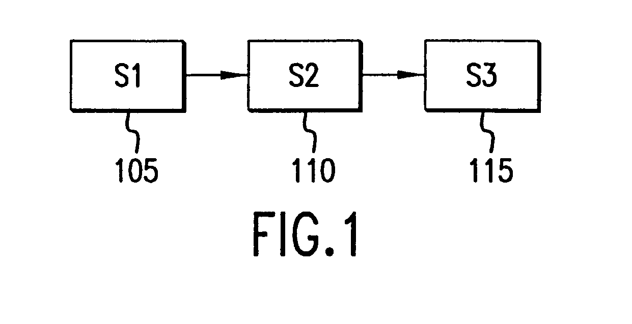
[0023]FIG. 1 illustrates typical stages involved in the processing of a reticle. In the first stage 105, the reticle is retrieved from a reticle cassette (that is, a reticle storage facility) by an end effector. In the second stage 110, the reticle...


PUM

PropertyMeasurementUnit
angleaaaaaaaaaa
angleaaaaaaaaaa
degrees of freedomaaaaaaaaaa

Abstract

An apparatus and method of transferring and loading a reticle onto a receiving station (for example, a reticle exposure stage). The reticle is first retrieved from a storage facility with an end effector having an reticle plate coupled to a mounting plate. The mounting plate connects the end effector to a robotic arm. The reticle is aligned in an out-of-plane position in an off-line alignment station. The alignment is in compliance with the alignment requirement at the receiving station. The reticle is mounted onto the reticle plate after undergoing the alignment at the off-line alignment station. The reticle is then transferred from the off-line alignment station to the receiving station while maintaining the previous alignment at the off-line alignment station. The apparatus further provides rigidity of the mounted reticle to ensure compliance with the alignment requirement at the receiving station.

Description

BACKGROUND OF THE INVENTION[0001]1. Field of the Invention[0002]The present invention relates generally to lithography systems. More particularly, the present invention relates to transferring and loading a reticle onto a receiving station while maintaining out-of-plane reticle alignment and providing rigidity of the reticle during the transfer.[0003]2. Background Art[0004]Lithography is a process used to create features on the surface of substrates. Such substrates can include those used in the manufacture of flat panel displays, circuit boards, various integrated circuits, and the like. A frequently used substrate for such applications is a semiconductor wafer. One skilled in the pertinent art would recognize that the description herein would also apply to other types of substrates known to those skilled in the pertinent art.[0005]During lithography, a wafer, which is disposed on a wafer stage, is exposed to an image projected onto the surface of the wafer by an exposure system lo...

Claims


Application Information

Patent Timeline
Patent Type & Authority Patents(United States)
IPC IPC(8): B66C1/00B65G49/07G03F7/20H01L21/027H01L21/677
CPCG03F9/7011G03F7/70741G03F9/00
Inventor FRIEDMAN, GLENN M.KOCHERSPERGER, PETERLAGANZA, JOSEPH
Owner ASML HLDG NV
Why Eureka
Try Eureka