
Smart lock with modified structure

a smart lock and modified technology, applied in the field of smart locks, can solve the problems of reducing the security performance of anti-theft doors, troublesome and inconvenient, and affecting people's daily life, and achieve the effect of convenient manipulation and simple structur

Active Publication Date: 2011-07-21
CMECH (GUANGZHOU) INDUSTRIAL LTD
View PDF9 Cites 19 Cited by
  • Summary
  • Abstract
  • Description
  • Claims
  • Application Information

AI Technical Summary

Benefits of technology

[0003]An advantage of the present utility model is to overcome the shortcomings and drawbacks in the prior art and provide a smart lock which is simple in structure, convenient in manipulation, safe and reliable and has a manual locking and unlocking function.
[0015]As compared with the prior art, the present utility model has the following advantageous effects:
[0016]1. The smart lock according to the present utility model exhibits a simple construction, less transmission components and easier manufacture and assembling, and is not liable to damage and easy to maintain;
[0017]2. The smart lock has a manual locking and unlocking function and is easy to operate and meanwhile has an electrical locking and unlocking function of ordinary smart locks, it is of low cost, safe and reliable and can be extensively applied to home and office anti-theft apparatuses.

Problems solved by technology

Heretofore, locks for anti-theft doors mostly employ manual locking and unlocking and are complicated in structure, troublesome and inconvenient.
However, when the control circuit or execution mechanism of such smart lock goes wrong, the lock cannot be duly repaired because professional repairers cannot reach the site timely or special component parts are lacked, whereupon the anti-theft doors cannot be locked or unlocked, thereby reducing security performance of the anti-theft door and causing great inconvenience to people's daily life.
Although nowadays, some smart locks with a manual locking or unlocking function are available in the market, but such locks exhibit complicated structures, many components, inconvenient and troublesome manipulation and high costs.

Method used


Image

  • Smart lock with modified structure
  • Smart lock with modified structure
  • Smart lock with modified structure

Examples


Embodiment Construction

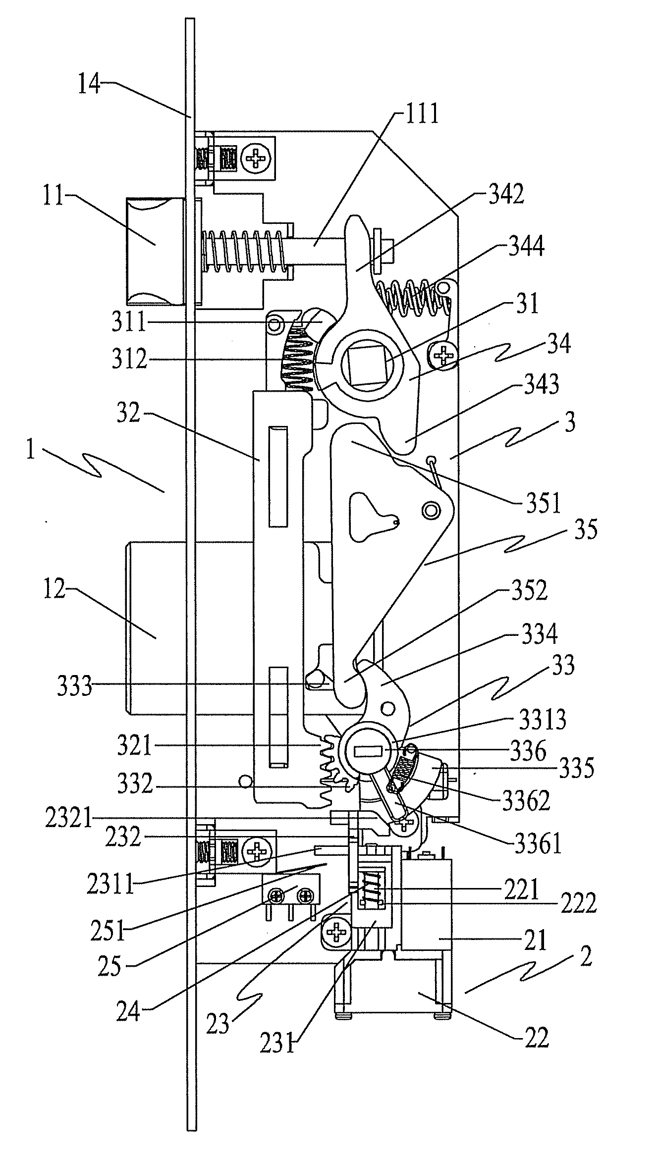
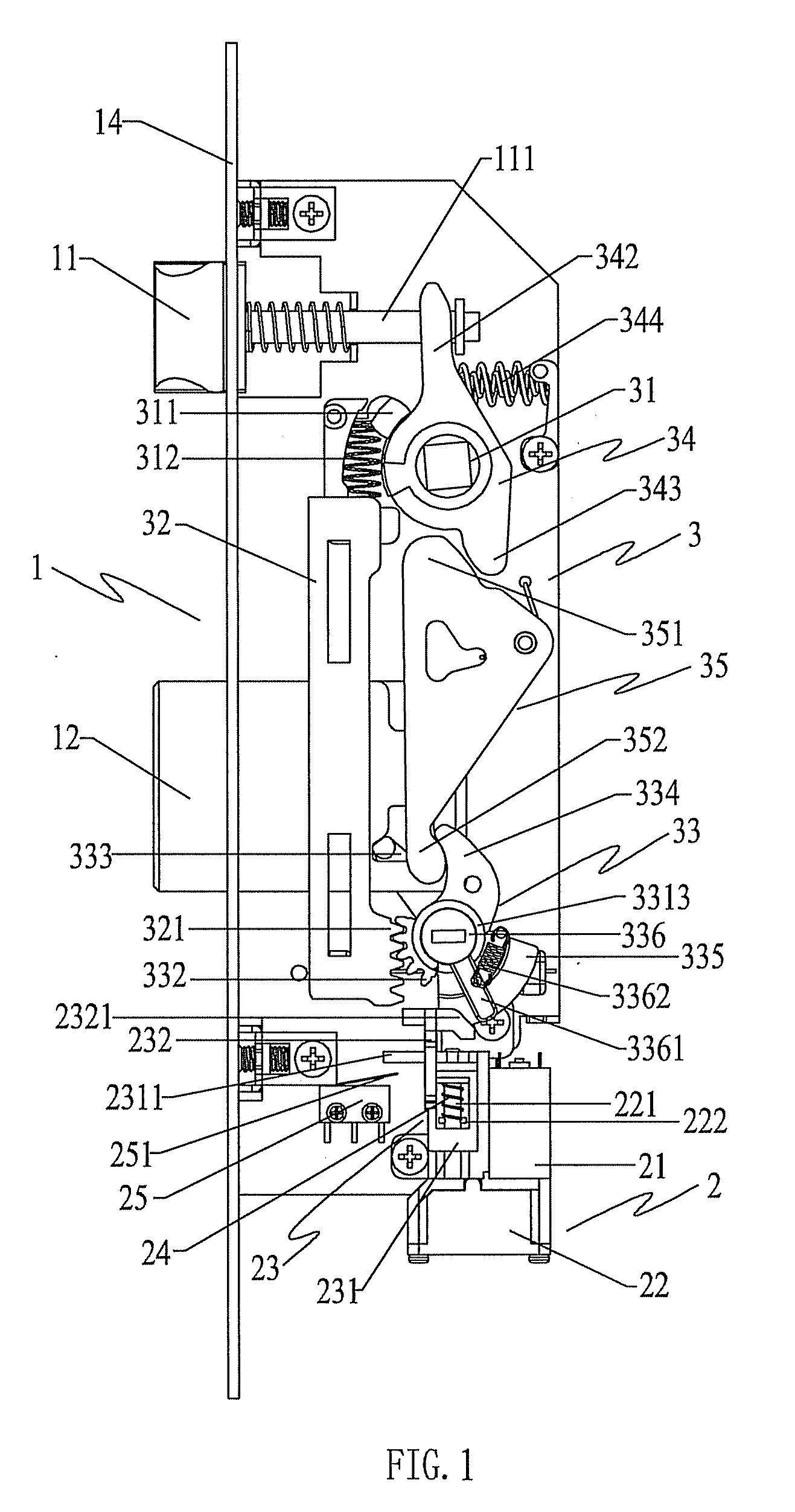
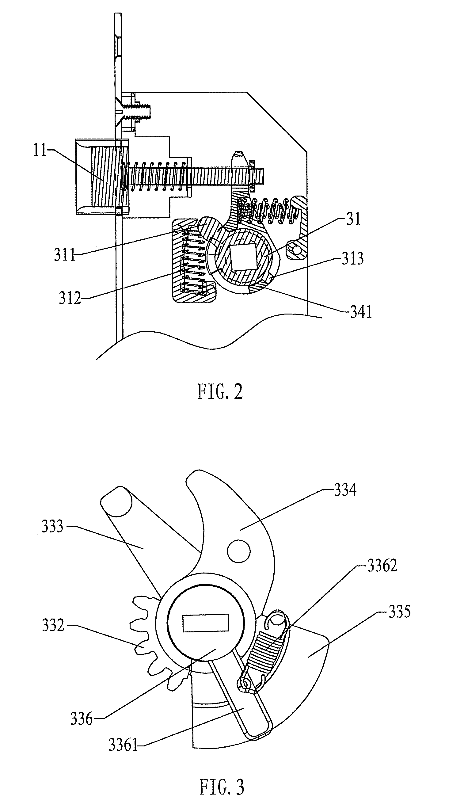
[0026]As shown in FIGS. 1-4, a smart lock with a modified structure according to the present utility model has a lock body 1 comprising an inner handle and an outer handle respectively disposed on an inner and outer end sides of a door body, a latch 11 and a bolt 12 extensible into and retractable from an end side of a door frame, an electrical locking mechanism 2 disposed in the lock body for interfering retraction of the bolt, and a manual locking and controlling mechanism 3 connected to the inner and outer handles and controlling opening and closing.

[0027]The manual locking and controlling mechanism 3 is provided with a rotation actuating piece 31 linked to the inner and outer handles and a bolt moving piece 33 controlling extension and retraction of the bolt, wherein the rotation actuating piece 31 is linked to the bolt moving piece 33 via a locking member to control the bolt 12 for locking when the inner and outer handles are lifted, and the rotation actuating piece 31 is linke...


PUM


Abstract

The present utility model discloses a smart lock with a modified structure comprising: a lock body including an inner handle and an outer handle, a latch and a bolt, an electrical locking mechanism for interfering retraction of the bolt; the lock body further comprises a manual locking and controlling mechanism connected to the inner and outer handles and controlling opening and closing; the manual locking and controlling mechanism is provided with a rotation actuating piece linked to the inner and outer handles and a bolt moving piece controlling extension and retraction of the bolt, wherein the rotation actuating piece is linked to the bolt moving piece via a locking member to control the bolt for locking when the inner and outer handles are lifted, and the rotation actuating piece is linked to the bolt moving piece via an unlocking member to control the bolt for unlocking when the inner and outer handles are pressed. The smart lock according to the present utility model has the following advantageous effects: 1. the smart lock exhibits a simple construction, less transmission components and easier manufacture and assembling, and is not liable to damage and easy to maintain; 2. the smart lock has a manual locking and unlocking function and is easy to operate and meanwhile has an electrical locking and unlocking function of ordinary smart locks, it is of low cost, safe and reliable and can be extensively applied to home and office anti-theft apparatuses.

Description

TECHNICAL FIELD[0001]The present utility model relates to a smart lock as an anti-theft apparatus, particularly a smart lock with a manually locking and unlocking function.BACKGROUND ART[0002]Heretofore, locks for anti-theft doors mostly employ manual locking and unlocking and are complicated in structure, troublesome and inconvenient. Therefore, professionals in the art develop and produce a smart lock which can be locked and unlocked automatically. Such lock generally comprises a bolt, an executing mechanism linked to the bolt, a motor bringing the execution mechanism into operation and a control circuit controlling the motor to work, wherein the control circuit controls the execution mechanism actuated by the motor, whereby the execution mechanism accomplishes locking or unlocking of the bolt. The operations of such lock are simple and quick. However, when the control circuit or execution mechanism of such smart lock goes wrong, the lock cannot be duly repaired because profession...

Claims


Application Information

Patent Timeline
IPC IPC(8): E05C1/08E05B47/06
CPCE05B47/0012E05B2047/0016E05B59/00Y10T292/1021Y10T70/7051Y10T292/57Y10T292/0837Y10T70/5239
Inventor DING, JUNLIANGZHOU, FUBIN
Owner CMECH (GUANGZHOU) INDUSTRIAL LTD
Features
  • Generate Ideas
  • Intellectual Property
  • Life Sciences
  • Materials
  • Tech Scout
  • Unparalleled Data Quality
  • Higher Quality Content
  • 60% Fewer Hallucinations
Learn More