Method for scanning projective capacitive touch panel

Inactive Publication Date: 2011-07-21
TPK TOUCH SOLUTIONS (XIAMEN) INC +1
View PDF6 Cites 37 Cited by
  • Summary
  • Abstract
  • Description
  • Claims
  • Application Information

AI Technical Summary

Benefits of technology

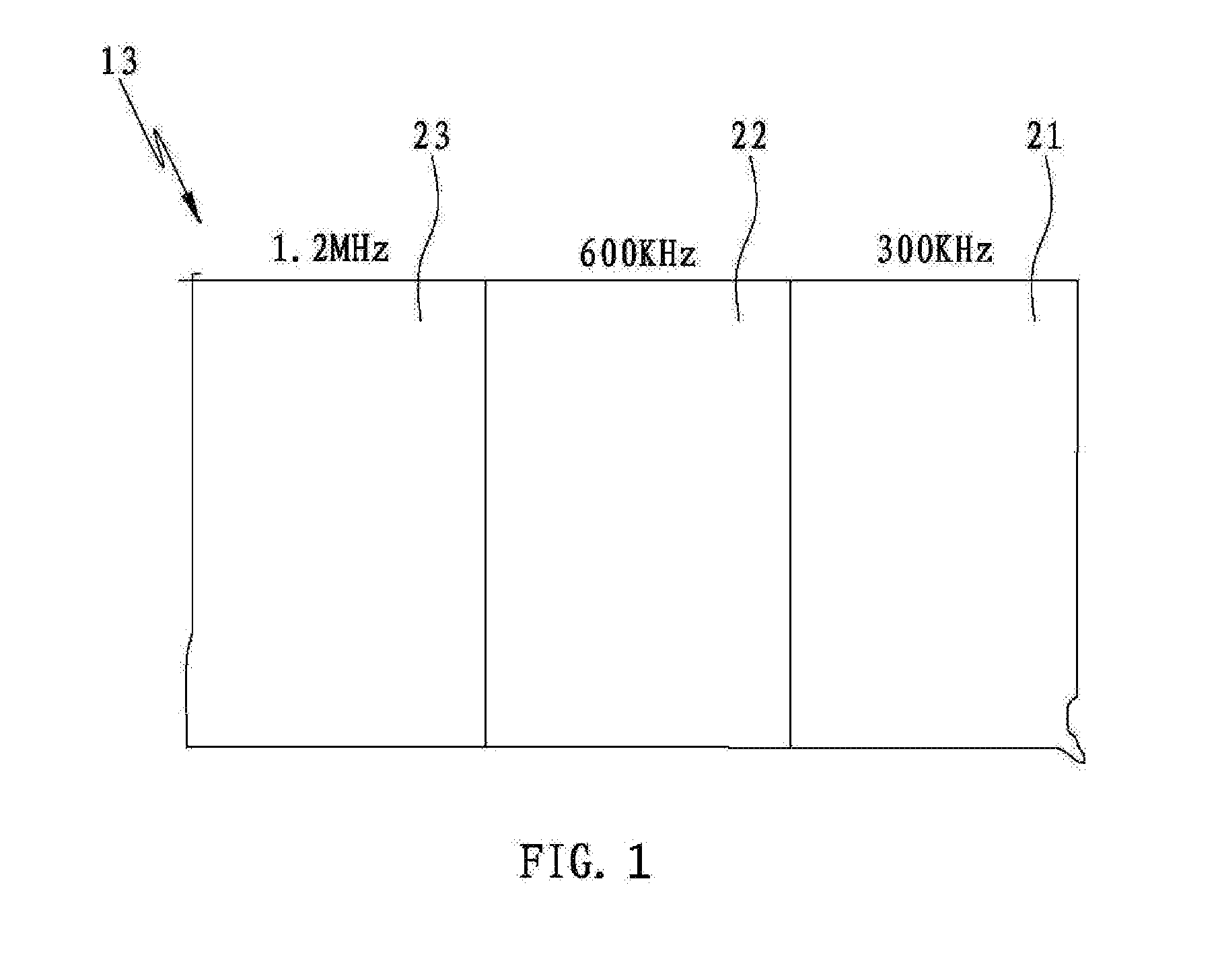
[0012]Thus, the method of the present invention uses different frequency excitation signals to scan different mutual capacitance groups according to the RC constant, which method can reduce the difference of the voltage between the mutual capacitance caused by the different RC constant and promote the scanning accuracy. Meanwhile, since the mutual capacitances which have lower RC constant are scanned by higher frequency excitation signal and mutual capacitance whic

Problems solved by technology

The conventional scanning method scans all the mutual capacitance by applying a constant frequency excitation signal, which will cause some problems.
In order to guarantee th

Method used


Image

  • Method for scanning projective capacitive touch panel
  • Method for scanning projective capacitive touch panel
  • Method for scanning projective capacitive touch panel

Examples


Embodiment Construction

[0018]In accordance with the usual meaning of “a” and “the” in patents, reference, for example to “an” electrode or “the” electrode is inclusive of one or more electrodes. In this application, the use of the singular includes the plural and vice versa unless specifically stated otherwise, for example, the term “mutual capacitance” includes singular and plural forms. The section headings used herein are for organizational purposes only, and are not to be construed as limiting the subject matter described.

[0019]The detailed description of the present invention will be discussed in the following embodiments, which are not intended to limit the scope of the present invention, but still can be adapted for other applications. While drawings are illustrated in details, it is appreciated that the quantity of the disclosed components could be greater or less than disclosed, except those components with express restricting amount.

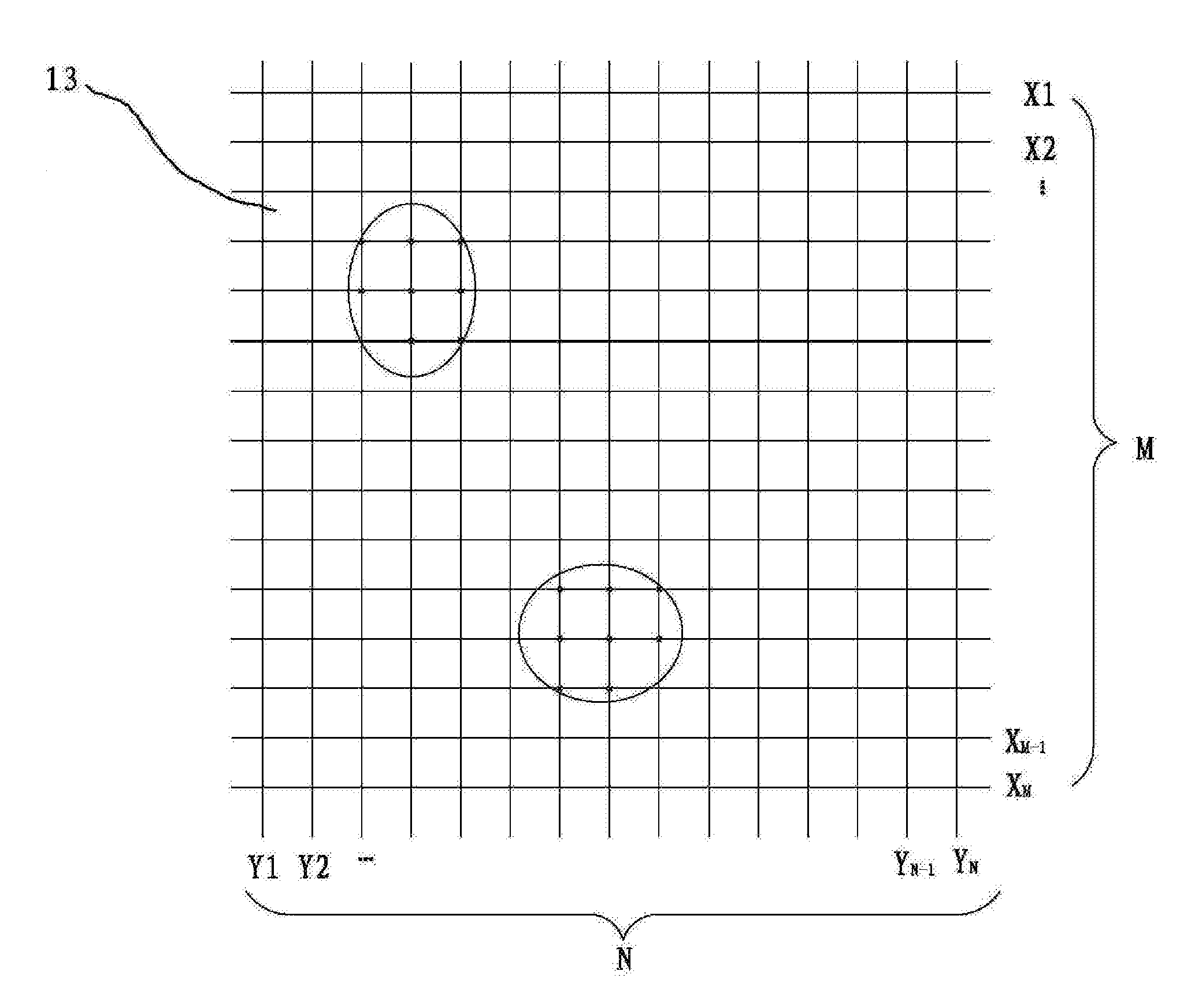
[0020]FIG. 3 is a top plan view of a projective capacitive touc...


PUM


Abstract

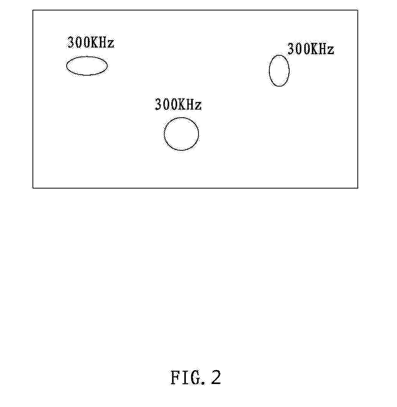
The present invention relates to a method for scanning a projective capacitive touch panel. The method includes the following steps: scanning the mutual capacitance that are divided into at least two groups by applying different frequency excitation signals to different mutual capacitance groups, wherein a frequency of a excitation signal applied to a mutual capacitance group with greater RC constant is lower than that of a excitation signal applied to a mutual capacitance group with smaller RC constant; obtaining a first current voltage of each mutual capacitance; comparing the first current voltage with a first reference voltage to obtain candidate mutual capacitance whose first current voltage exceed the first reference voltage by a first threshold value; scanning the candidate mutual capacitance by applying a low frequency excitation signal; obtaining a second current voltage of each candidate mutual capacitance; comparing the second current voltage of each candidate mutual capacitance with a corresponding second reference voltage to obtain touched mutual capacitance whose second current voltage exceed the corresponding second reference voltage by a second threshold value.

Description

BACKGROUND OF THE INVENTION[0001]1. Field of the Invention[0002]This application claims the benefit of People's Republic of China. Application No 201010103958.5, filed on Jan. 21, 2010.[0003]The present invention generally relates to a method for scanning a projective capacitive touch panel.[0004]2. Description of the Related Art[0005]Capacitive touch panels are divided into projective capacitive touch panels and surface capacitive touch panels. Different touch panels adopt different principles according to different configurations. The projective capacitive touch panel is disposed on a substrate with the other surface of the projective capacitive touch panel attached to the substrate. A controller electrically connects to the projective capacitive touch panel for driving the projective capacitive touch panel.[0006]The projective capacitive touch panel includes two layers of conductive electrodes orthogonally placed. One layer of conductive electrodes includes first-axis electrodes ...

Claims


Application Information

Patent Timeline
IPC IPC(8): G06F3/045
CPCG06F3/044G06F3/0416G06F3/04166G06F3/0446
Inventor WANG, WANQIULIN, CHUN-CHI
Owner TPK TOUCH SOLUTIONS (XIAMEN) INC
Why Eureka
Try Eureka