Backplane cable interconnection

Active Publication Date: 2011-07-21
OHIO ASSOCD ENTERPRISES
View PDF58 Cites 54 Cited by
  • Summary
  • Abstract
  • Description
  • Claims
  • Application Information

AI Technical Summary

Benefits of technology

[0025]According to still another aspect of the invention, a shroud for surrounding contacts of a backplane, the shroud including: a main body having slots therein for receiving stacked cable end modules; and a pair of side brackets at opposite ends of the main body. The main bo

Problems solved by technology

Such modules are expensive, allow limited flexibility,

Method used


Image

  • Backplane cable interconnection
  • Backplane cable interconnection
  • Backplane cable interconnection

Examples


Embodiment Construction

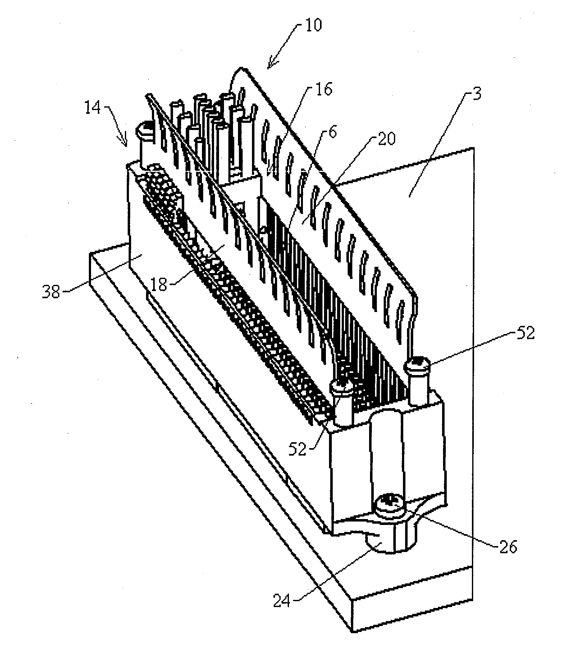
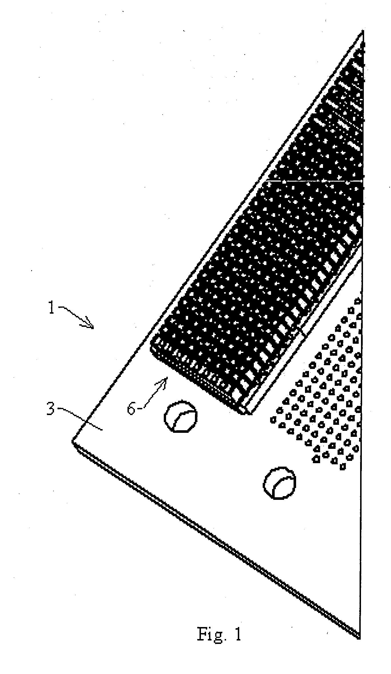
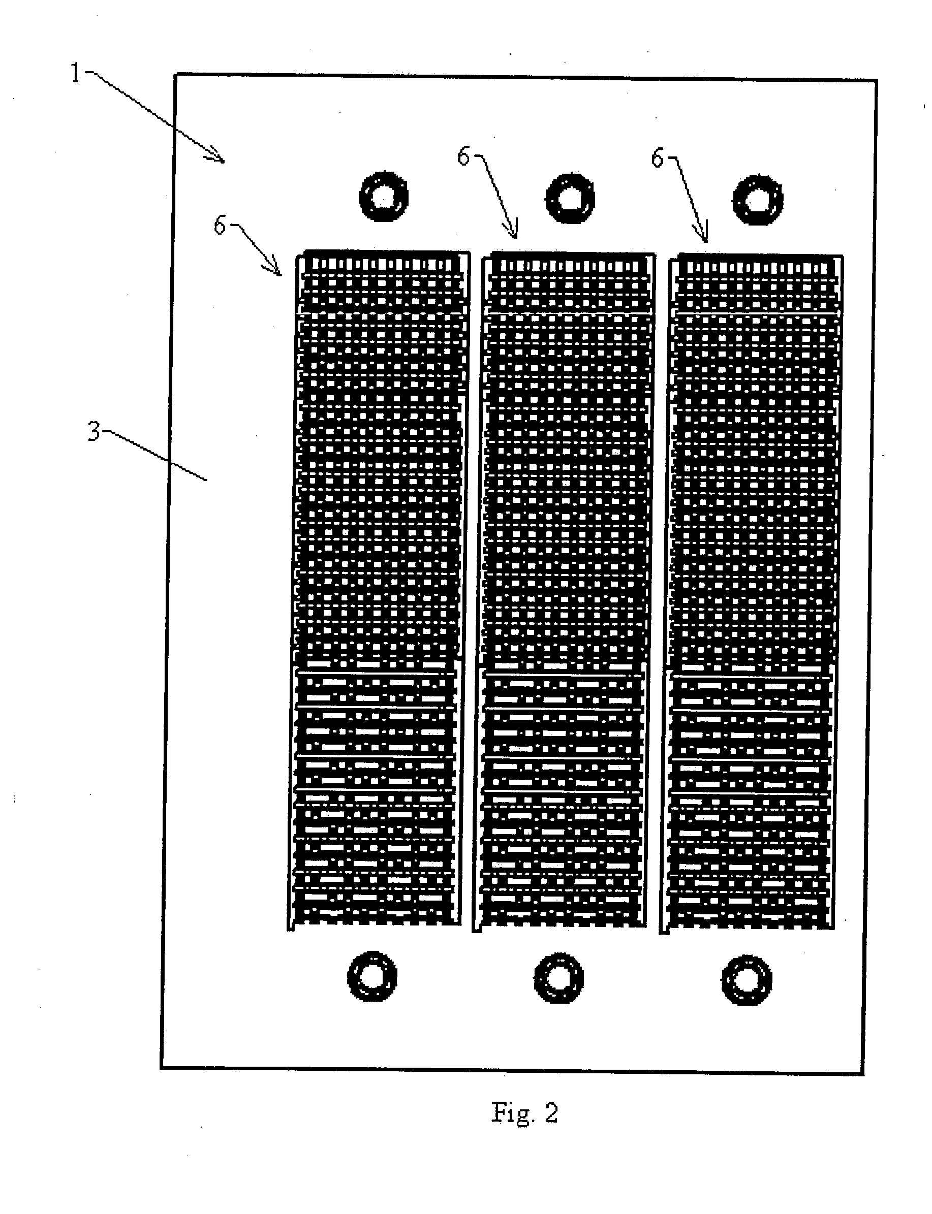
[0040]A backplane cable interconnection is used to engage a backplane connector on a backplane. The backplane cable interconnection includes a shroud that that fits around the backplane connector, and a series of cable end modules that are inserted into the shroud. The shroud and the modules are used in place of rear transition modules. Such rear transition modules are fundamentally very expensive because of size and complexity; and, therefore, are not easily replaced with new designs. Also, backplane circuitry, such as that in rear transition modules, has electrical losses that are greater than cable losses. The present interconnection satisfies a need that exists for a connection method that will allow backplane circuit rerouting with small electrical losses, while allowing the ability to be easily changed without large investment. Also, a need exists for a backplane interconnection that will allow direct cabling between the backplane and the enclosure or between the backplane and...


PUM


Abstract

A backplane cabling interconnect scheme is provided that includes a wafer based cable termination and an organizer shroud. The shroud complements existing backplane connectors and provides positioning and polarization for the cable terminated wafer. The wafer cable ends can be stacked or arranged in various arrays and are held in place with an integral latch. A permanent latch is provided for high vibration environments.

Description

[0001]This application claims priority under 35 USC 119 to U.S. Provisional Application No. 61 / 296,635, filed Jan. 20, 2010, which is incorporated herein by reference in its entirety.BACKGROUND OF THE INVENTION[0002]1. Field of the Invention[0003]The invention relates generally to cable interconnection at the backplane of computers.[0004]2. Description of the Related Art[0005]Modern electronic systems such as computer systems, telephonic switches and the like, often include large circuit boards called backplane boards that are rack mounted or retained in cabinets and are electrically connected to a number of smaller circuit boards called daughter cards. Various functions on the daughter cards are transferred between cards via the backplane. Examples of such configurations may be found in U.S. Pat. Nos. 6,824,391, 6,267,604, and 6,171,115.[0006]FIGS. 1 and 2 show an example of a connection scheme 1 that allows multiple daughter cards to be connected to a common backplane or motherboa...

Claims


Application Information

Patent Timeline
IPC IPC(8): H01R12/00H01R13/62
CPCH01R9/0515H01R13/405H01R2201/06H01R13/6471H01R13/6273
Inventor CROFOOT, LARRY M.VENALECK, JOHN T.
Owner OHIO ASSOCD ENTERPRISES
Why Eureka
Try Eureka