HF Coupler or HF Power Splitter, Especially a Narrow-Band and/or 3DB Coupler or Power Splitter

a power splitter and narrowband technology, applied in the direction of electrical devices, multiple-port networks, coupling devices, etc., can solve the problems of high space requirements, relatively large electrical losses, and high cost of high-quality pcb materials, and achieve low space requirements, high directional focus, and low electrical losses

Inactive Publication Date: 2009-02-26
KATHEIN WERKE KG
View PDF10 Cites 8 Cited by
  • Summary
  • Abstract
  • Description
  • Claims
  • Application Information

AI Technical Summary

Benefits of technology

[0027]By way of an exemplary illustrative non-limiting solution, a power splitter or coupler can be produced with extremely low space requirement, of which the electrical parameters are within broad limits comparatively freely adjustable or pre-selectable. In particular, it has low electrical losses. In addition to this, the exemplary illustrative non-limiting power splitter or coupler is also characterized by its high directional focus. It is above all characterized by the fact that the exemplary illustrative non-limiting coupler or power splitter—which is generally built into a housing—also has a distance interval from the housing in the region of the lower coupling zone, i.e., a housing wall, thus no fixed dielectric is provided immediately adjacent and a lower ∈ is realized and attained which has a positive effect on the electrical properties of the coupler or power splitter. As a result, the exe

Problems solved by technology

For higher degrees of coupling, such as are needed for a power splitter, these distance intervals are often very small or even too small to be capable of being manufactured economically.
As a result of the relatively high attenuation of the microstrip conduction and its sensitivity to fluctuations in the dielectric constants, the disadvantages of these couplers lie in the high space requirement and the relatively great electrical losses and the high costs of high-quality PCB material.
The disadvantages of the directional coupler in suspended-substrate technology are, on the one hand, high demands on the positioning of the substrate between the two earthing surfaces (problems arise here with the correct positioning in the horizontal but also with regard to the exact consideration of the distance intervals between the cover and the base).
These requirements for correct or optimum positioning incur high costs for the mechanical processing and assembly.
This is often disadvantageous with regard to the possibility of reuse or the attainment of adequate flexibility with regard to the realisation and implementation of a selected concept for a coupler, as well as for its use for further applications.
In addition to this, from the electrical point of view, with this technology it is only possible with difficulty to compensate for the different phase velocities of the

Method used


Image

  • HF Coupler or HF Power Splitter, Especially a Narrow-Band and/or 3DB Coupler or Power Splitter
  • HF Coupler or HF Power Splitter, Especially a Narrow-Band and/or 3DB Coupler or Power Splitter
  • HF Coupler or HF Power Splitter, Especially a Narrow-Band and/or 3DB Coupler or Power Splitter

Examples


Embodiment Construction

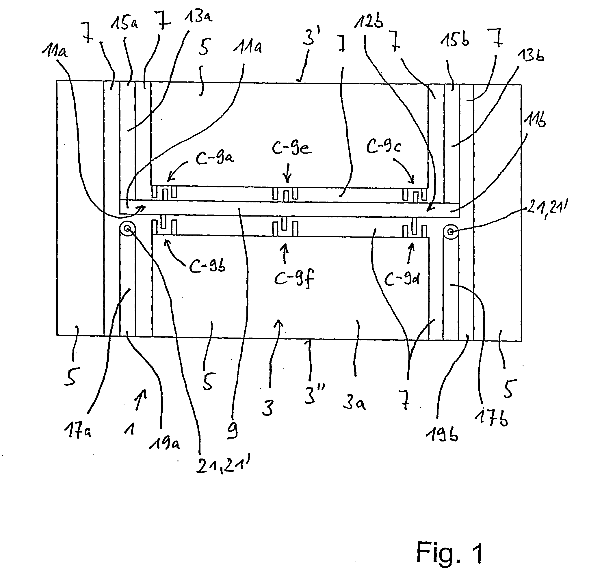
[0035]FIG. 1 shows a plan view of a first exemplary illustrative non-limiting coupler or power splitter 1 which is formed on a substrate 3 in the form of a printed circuit board.

[0036]Visible on the substrate 3 are four surface areas 5, on the upper side 3a of the substrate visible in FIG. 1, which are electrically-galvanically separated from one another by cut-outs 7. This surface area 5 involves earthing surfaces 5.

[0037]Formed in the cut-outs 7 is a first coupling zone 9 in stripline technology, which runs in a first direction or longitudinal direction on the substrate 3.

[0038]Provided at the beginning 11a and end 11b of this coupling zone 9, running transversely, are a first and second connection line 13a and 13b, which lead to connections 15a and 15b on the one substrate edge 3′.

[0039]The non-conductive cut-out area 7 shown in the plan view of the exemplary illustrative non-limiting implementation according to FIG. 1 is formed as H-shaped. In the immediate extension of the conn...


PUM


Abstract

An improved HF coupler or HF power splitter comprises four connection lines arranged on the same side of the substrate. Two coupling zones are formed on the substrate on two opposite sides; the second coupling zone is connected to the associated connection lines arranged on the side of the substrate opposing the coupling zone, by means of two via holes in an electroplated manner. The capacitors provided at the beginning and at each end of each coupling zone are respectively embodied as interdigital capacitors; and the capacitors are respectively coupled to earth.

Description

CROSS-REFERENCES TO RELATED APPLICATIONS[0001]This application is the U.S. national phase of International Application No. PCT / EP2006 / 002189, filed 9 Mar. 2006, which designated the U.S. and claims priority to German Patent Application No. 10 2005 016 054.9, filed 7 Apr. 2005, the entire contents of each of which are hereby incorporated by reference.FIELD[0002]The technology herein relates to an HF coupler or HF power splitter, especially a narrow-band HF coupler or HF power splitter.BACKGROUND AND SUMMARY[0003]In high-frequency technical systems it is often necessary for a signal, for example with a power P, to be split into two signals with a power of P / 2 each. To do this, ring couplers are frequently used. Such ring couplers are known, for example, from Zinke Brunswig, “High-frequency Technology”, Springer-Verlag, 6th Edition, 2000, and specifically page 192.[0004]These ring couplers are frequently designed in microstrip conductor technology.[0005]In addition to this, however, hi...

Claims


Application Information

Patent Timeline
IPC IPC(8): H01P5/18
CPCH01P5/187
Inventor ROTTMOSER, FRANZHEROLD, JOACHIM
Owner KATHEIN WERKE KG
Why Eureka
Try Eureka