Rotatable and concealable electrical power receptacle

a technology of electrical power receptacles and receptacles, which is applied in the direction of flexible/turnable line connectors, office tables, coupling device connections, etc., can solve the problems of lack of degree of convenience of use, lack of comfort of use of conventional electrical power outlets, and mass use of space, so as to reduce the overall manufacturing cost, simplify the structure design, and maintain the appearance of tidy space of us

Active Publication Date: 2011-07-21
POWERTECH INDAL
View PDF28 Cites 30 Cited by
  • Summary
  • Abstract
  • Description
  • Claims
  • Application Information

AI Technical Summary

Benefits of technology

[0006]In view of the aforementioned issues, a primary objective of the present invention is to provide a rotatable and concealable electrical power receptacle in accordance with the structural design thereof for solving the inconvenience of use associated with the conventional electrical power outlet. The rotatable and concealable electrical power receptacle according to the present invention is rotatable to an exposed state in use or a concealed state when not in use, so that the overall space of use can be maintained in a tidy appearance. Moreover, the rotatable and concealable electrical power receptacle according to the present invention simplifies the structure design, thereby decreasing the overall manufacturing cost.

Problems solved by technology

Thus, as a variety of electronic devices require their own power cables for connecting to electrical sockets, the plurality of power cables extending out from their own main body to the electrical sockets causes the operating platform and the use of space to be in a mass and not tidy.
As such, the conventional electrical power outlets are not comfort in use and lacking the degree of convenience of use.

Method used


Image

  • Rotatable and concealable electrical power receptacle
  • Rotatable and concealable electrical power receptacle
  • Rotatable and concealable electrical power receptacle

Examples


first embodiment

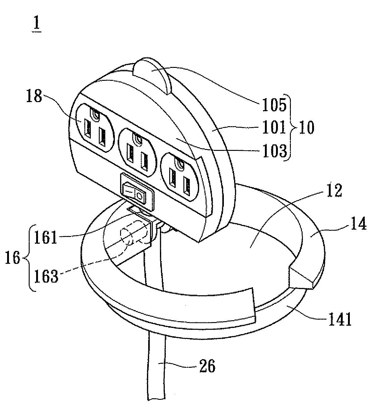
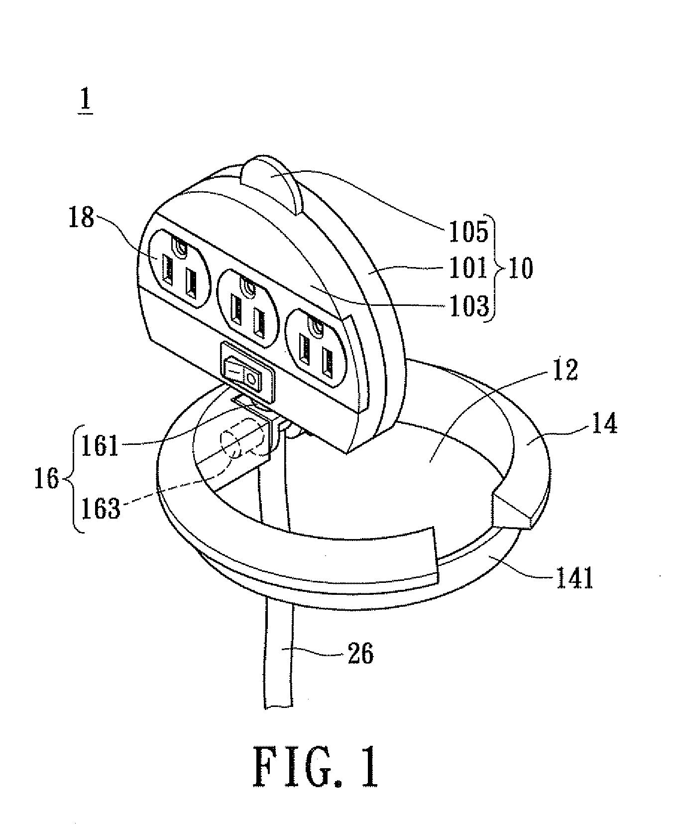
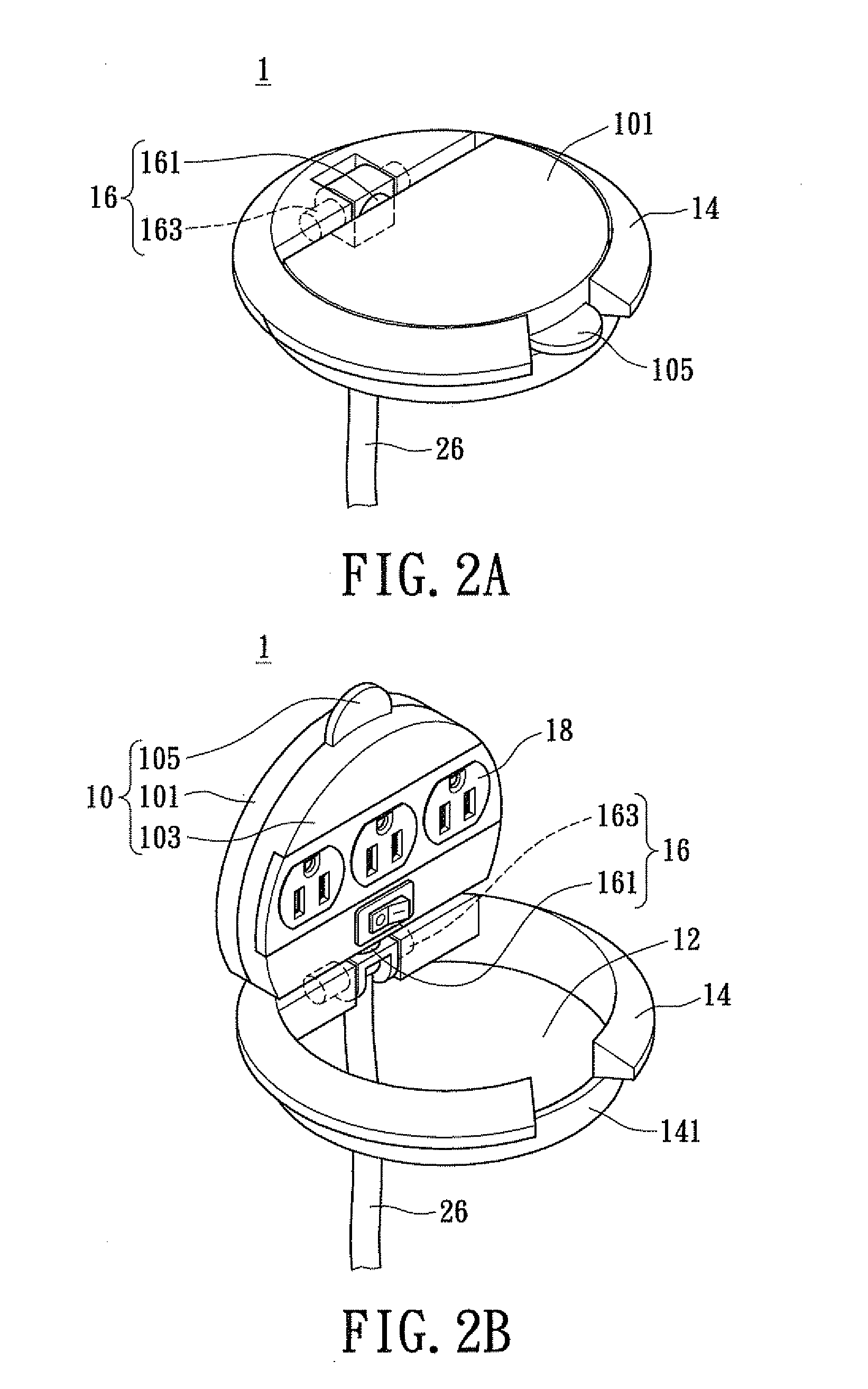
[0018]First please refer to FIG. 1, in which an exploded diagram of the rotatable and concealable electrical power receptacle in accordance with certain aspects of the present technique is demonstrated. A rotatable and concealable electrical power receptacle 1 comprises: a main body 10, a shaft section 16, an accommodating section 14, and at least one electrical outlet assembly 18. The main body 10 further includes a first housing member 101, a second housing member 103, and a pulling member 105. The shaft section 16 further includes a first shaft member 161 and a second shaft member 163. The first shaft member 161 contains an electrical power cable 26 disposed inside it. The accommodating section 14 has an interior space forming as a receiving space 12 and incorporates with the pulling member 105 to dispose an accommodating space 141 for receiving the pulling member 105. The accommodating space 141 is adjacent to the receiving space 12.

[0019]The first housing member 101 and the sec...

second embodiment

[0027]Finally, please refer to FIG. 3 in conjunction with FIG. 3A, in which a diagram of a second embodiment in accordance with the rotatable and concealable electrical power receptacle according to the present invention in use is demonstrated. Further, the FIG. 3A is an exploded diagram of the A portion in FIG. 3. In the embodiment, components and their connection relationship of the rotatable and concealable electrical power receptacle 1a are identical with that shown in FIG. 1. However, as per the embodiment shown in FIG. 3 and FIG. 3A, the electrical outlet assemblies 18a may include not only electrical outlets but also USB jack assemblies 24a. The USB jack assemblies 24a may be disposed on the main body 10, either on the first housing member 101a or the second housing member 103a. The quantity of the USB jack assemblies 24a and the configuration in series or in parallel order in accordance with the embodiment is merely for illustration, but it not limited thereto. The main body...


PUM


Abstract

Disclosed is a reversible and concealable electrical power receptacle, comprising: a main body, a shaft section, an accommodating section, and an electrical outlet assembly. The electrical outlet assembly is disposed on the main body; the accommodating section is for receiving the main body; the shaft section, comprises a first shaft member and a second shaft member. The second shaft member, being coupled to the main body and is perpendicular to the first shaft member, and the main body is rotatable with respect to the first and the second shaft members transversely respectively. Consequently, the main body is able to rotate transversely and perpendicularly with respect to the accommodating section in accordance with the rotational movements of the first shaft and the second shaft members, for resulting in an exposed state in use or a concealed state when not in use, thereby achieving effective space utilization.

Description

BACKGROUND OF THE INVENTION[0001]1. Field of the Invention[0002]The present invention relates to an electrical power receptacle, in particular, to an electrical power receptacle which is rotatable and concealable.[0003]2. Description of Related Art[0004]With the present continuous development of modern society, more and more electronic devices are utilized in public. To operate the electronic devices, electrical power supplies are required to drive the electronic devices. Generally speaking, each electronic device requires at least one power cable for connecting to an electrical socket to receive public electrical power. Thus, as a variety of electronic devices require their own power cables for connecting to electrical sockets, the plurality of power cables extending out from their own main body to the electrical sockets causes the operating platform and the use of space to be in a mass and not tidy.[0005]In addition, standard electrical extension outlets, connected to the public e...

Claims


Application Information

Patent Timeline
Patent Type & Authority Applications(United States)
IPC IPC(8): H01R13/44
CPCA47B21/06H01R35/02H01R25/006A47B2021/066
Inventor LIN, MEI-JU
Owner POWERTECH INDAL
Why Eureka
Try Eureka