Apparatus and methods for improved stent deployment

a technology of stent and stent body, applied in the field of medical devices, can solve the problems of unfavorable or difficult recapture or repositioning of stent, unfavorable stent positioning, and inability to move an undesired amount, and achieve the effect of improving the positioning of sten

Active Publication Date: 2011-07-21
COOK MEDICAL TECH LLC
View PDF27 Cites 77 Cited by
  • Summary
  • Abstract
  • Description
  • Claims
  • Application Information

AI Technical Summary

Benefits of technology

Advantageously, the provision of a delivery system employing the apparatus and methods described herein may permit improved positioning of a stent, or stent-graft, inside of a body passage. The apparatus and methods also permit an amount of recapture of a stent prior to full deployment. Moreover, any undesirable foreshortening, which typically occurs when conventional trigger wires release a stent, may be reduced or eliminated by use of the control member and associated tine members.

Problems solved by technology

Barbs of the stent may engage the body passage, and the deployed stent may be difficult or impossible to recapture or reposition at this time.
Further, upon release of the trigger wire, as the stent is expanding it may foreshorten or otherwise move an undesired amount with respect to the body passage.
Therefore, the actuation of a conventional trigger wire may yield inaccurate positioning of a stent that engages a body passage and may be difficult to retrieve.
The problems are manifest not only in the deployment of stents but also in the deployment of stent grafts and other implantable medical devices.

Method used


Image

  • Apparatus and methods for improved stent deployment
  • Apparatus and methods for improved stent deployment
  • Apparatus and methods for improved stent deployment

Examples


Embodiment Construction

In the present application, the term “proximal” refers to a direction that is generally closest to the heart during a medical procedure, while the term “distal” refers to a direction that is furthest from the heart during a medical procedure.

The preferred embodiments taught below are described in connection with the deployment of a stent or stent graft. It is to be understood that the apparatus and method can be used for deploying of a range of implantable medical devices including stents, stent grafts, vena cava filters, occlusion devices and so on.

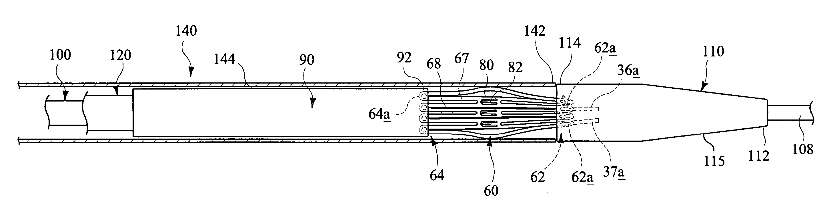
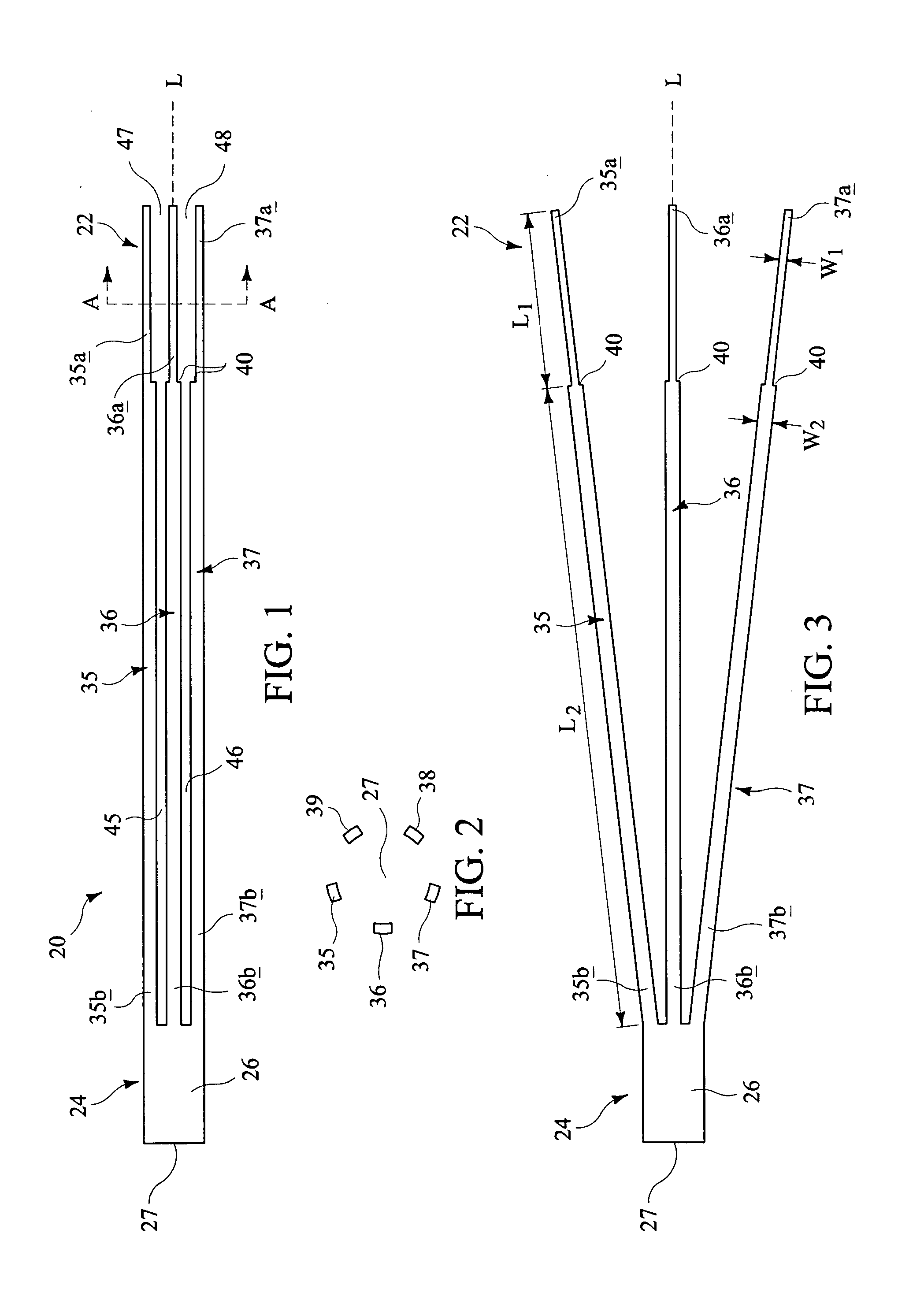
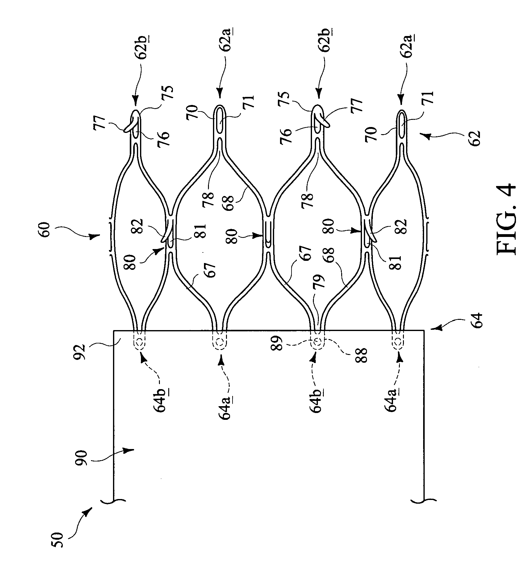
Referring to FIGS. 1-3, an apparatus for deploying a stent, or stent-graft, is disclosed. The apparatus comprises a control member 20 having proximal and distal regions 22 and 24. The control member 20 may be formed from a cannula 26 having a lumen 27 extending between the proximal and distal regions 22 and 24. As described further below, selective actuation of the control member 20 may permit at least partial radial expansion of a stent...


PUM


Abstract

Apparatus for facilitating deployment of a an implantable medical device includes a control member (20) having at least one tine member (35-37). A proximal region (35b-37b) of at least one of the tine members (35-37) is configured to engage an associated portion of a stent (60). In use, the control member (20) comprises a contracted delivery configuration in which the proximal region of the at least one of the tine member (35-37) is radially contracted, to radially constrain the associated portion of the stent (60). The control member (20) also comprises an expanded configuration in which the proximal region of the at least one of the tine member (35-37) expands radially outward relative to the central longitudinal axis to allow the stent to engage a body passage. The proximal region of the at least one tine member (35-37) is selectively movable an incremental amount between the contracted and expanded configurations, in radially inward and outward directions, to facilitate positioning of the stent (60) within the body passage.

Description

TECHNICAL FIELDThe present invention relates generally to medical devices, and more particularly, to apparatus and methods for improved deployment of stents or other implantable medical devices.BACKGROUND ARTStents may be inserted into an anatomical vessel or duct for various purposes. Stents may maintain or restore patency in a formerly blocked or constricted passageway, for example, following a balloon angioplasty procedure. Other stents may be used for different procedures, for example, stents placed in or about a graft have been used to hold the graft in an open configuration to treat an aneurysm. Additionally, stents coupled to one or both ends of a graft may extend proximally or distally away from the graft to engage a healthy portion of a vessel is wall away from a diseased portion of an aneurysm to provide endovascular graft fixation.Stents may be either self-expanding or balloon-expandable, or they can have characteristics of both types of stents. Self-expanding stents may ...

Claims


Application Information

Patent Timeline
Patent Type & Authority Applications(United States)
IPC IPC(8): A61F2/84
CPCA61F2/915A61F2/95A61F2/966A61F2002/91591A61F2002/9511A61F2230/0013A61F2002/9665A61F2220/0016A61F2220/0058A61F2220/0075A61F2002/9534A61F2/9661
Inventor HASELBY, KENNETH
Owner COOK MEDICAL TECH LLC
Why Eureka
Try Eureka