

Cooling apparatus
a technology of cooling apparatus and cooling chamber, which is applied in lighting and heating apparatus, semiconductor lasers, and semiconductor/solid-state device details. it can solve the problems of dew condensation and increase in power consumption, and achieve the effect of reducing the temperature difference between the endothermic side and the exothermic side of each peltier device and reducing the power consumption of the peltier devi
- Summary
- Abstract
- Description
- Claims
- Application Information
AI Technical Summary
Benefits of technology
Problems solved by technology
Method used
Image

Examples
embodiment 1
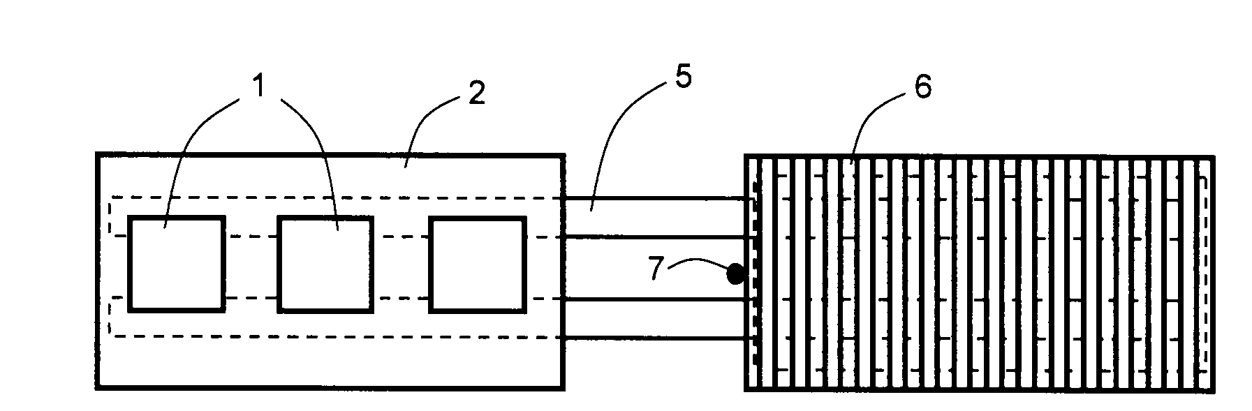
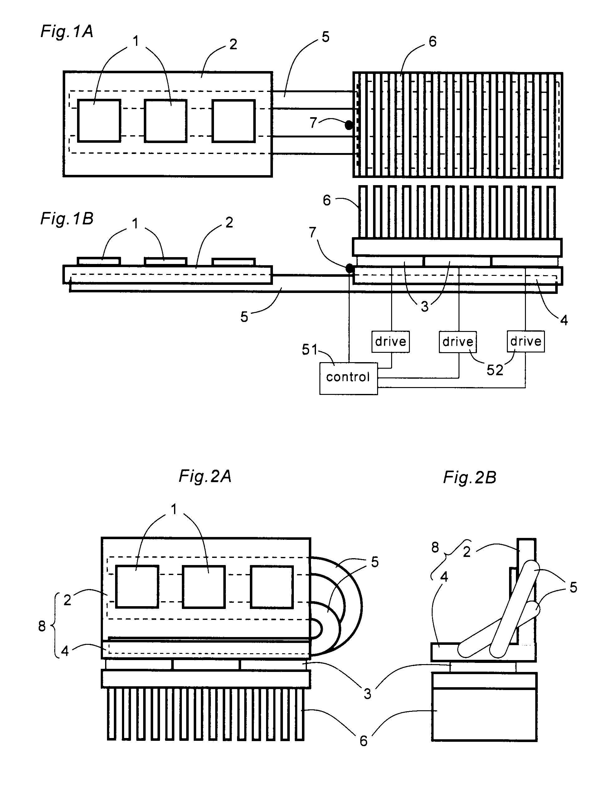
[0035]FIGS. 1A and 1B are a plan view and a front view, showing a cooling apparatus according to Embodiment 1 of the present invention. This cooling apparatus includes a heat receiving plate 2, a radiator plate 4, thermal transport heat pipes 5, a plurality of Peltier devices 3 and a heat sink 6.
[0036]The heat receiving plate 2 is made of a material having favorable thermal conductivity, like a metallic material such as copper or aluminum. An upper surface of the heat receiving plate 2 has a flat shape, on which a plurality of heating elements 1 such as semiconductor lasers are mounted. FIG. 1 shows one example in which three heating elements 1 are mounted, but the number of the heating elements 1 may be two or four or more. A lower surface of the heat receiving plate 2 has a shape substantially conforming to a shape of each of the thermal transport heat pipes 5, thereby ensuring favorable thermal coupling.
[0037]The thermal transport heat pipes 5 are constituted such that working fl...
embodiment 2
[0051]FIGS. 2A and 2B are a front view and a side view, showing a cooling apparatus according to Embodiment 2 of the present invention. This cooling apparatus has a configuration similar to that shown in FIG. 1, but is different in that each thermal transport heat pipe 5 is bent in a U-shape, and a heat receiving and radiating plate 8 is used in which the heat receiving plate 2 and the radiator plate 4 shown in FIG. 1 are integrated into a single piece and disposed perpendicularly to each other. With such a configuration, it is possible to realize downsizing of the entire apparatus. The temperature control circuit of the cooling apparatus has the same configuration as that shown in FIG. 1, and therefore not shown in the drawing.
[0052]The thermal transport heat pipe 5 according to this embodiment can be a common heat pipe including a circular pipe, a grooved pipe, a wire-lined pipe, or a particle sintered pipe. However, when bending the heat pipe more than one time, a problem may occ...
embodiment 3
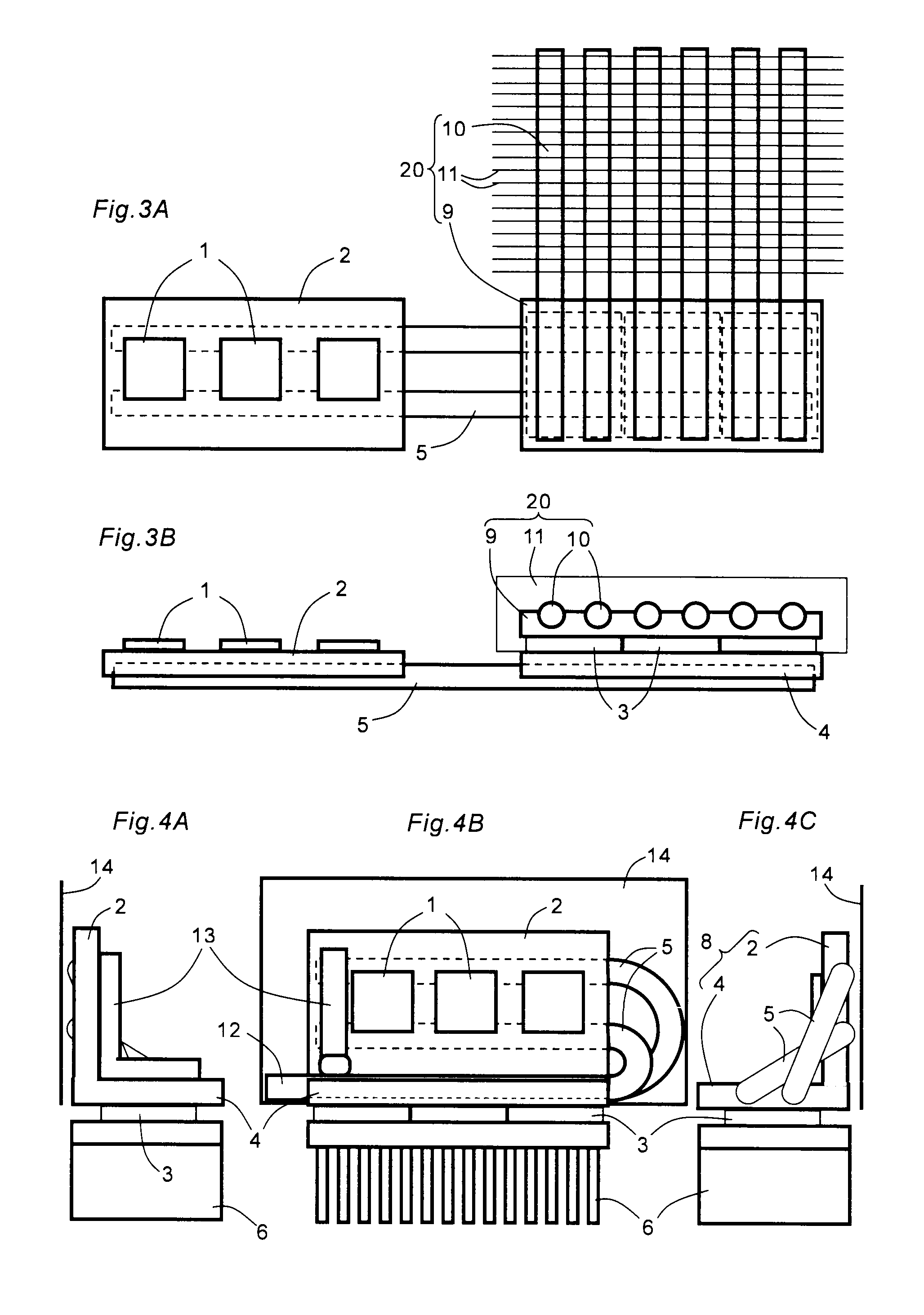
[0056]FIGS. 3A and 3B are a plan view and a front view, showing a cooling apparatus according to Embodiment 3 of the present invention. This cooling apparatus includes the heat receiving plate 2, the radiator plate 4, the thermal transport heat pipes 5, the plurality of Peltier devices 3, and a heat dissipating unit 20. The cooling apparatus has a configuration similar to that shown in FIG. 1, but is different in that the heat dissipating unit 20 including radiating heat pipes 10 is used in place of the heat sink 6 shown in FIG. 1. The temperature control circuit of the cooling apparatus has the same configuration as that shown in FIG. 1, and therefore not shown in the drawing.
[0057]The heat dissipating unit 20 includes a second heat receiving plate 9 in contact with the exothermic side of each Peltier device 3, the plurality of radiating heat pipes 10 coupled to the second heat receiving plate 9, and radiating fins 11 coupled to the respective radiating heat pipes 10.
[0058]The seco...
PUM
 Abstract
Description
Claims
Application Information