Rotary Tablet Press and Method for Pressing Tablets in a Rotary Tablet Press

a tablet press and rotary technology, applied in the field of rotary tablet presses, can solve the problems of not always satisfying known procedures, tablets to be pressed do not always achieve the required fracture resistance, and cracks form in the pellets, so as to reduce the tendency of cover, avoid air inclusions, and avoid known procedures.

Active Publication Date: 2011-07-28
FETTE COMPACTING GMBH
View PDF3 Cites 2 Cited by
  • Summary
  • Abstract
  • Description
  • Claims
  • Application Information

AI Technical Summary

Benefits of technology

[0012]Thus, according to the invention, air inclusions are substantially avoided. Thereby, inner tensions in the pellets are avoided, and the cover tendency is also reduced. This, in turn, minimizes tablet waste. At the same time, a higher fracture resistance and, in particular, the respectively required fracture resistance, is attained with a lower compression force. This in turn leads to an improved running smoothness of the press, and with it, to lower sound emissions. Also as a result, the wear, particularly of the press devices such as the compression rollers and the punch heads interacting with them, is reduced. The energy expenditure per tablet produced can be reduced, which also results in a cost reduction. According to the invention, the possibility of direct compression also exists. Thus, in the prior art, the powder to be compressed is frequently fed in advance to a granulating process in order to improve the subsequent suitability for tabletting the press masses in the press. According to the invention, this costly granulating process can be omitted.

Problems solved by technology

During tablet pressing in such tablet presses, a problem arises in the so-called covers in which cracks form within the pellets when the tablets are ejected out of the die holes.
A further problem exists in that the tablets to be pressed do not always attain the required fracture resistance.
In practice, however, the known procedure does not always lead to satisfactory results.

Method used


Image

  • Rotary Tablet Press and Method for Pressing Tablets in a Rotary Tablet Press
  • Rotary Tablet Press and Method for Pressing Tablets in a Rotary Tablet Press
  • Rotary Tablet Press and Method for Pressing Tablets in a Rotary Tablet Press

Examples


Embodiment Construction

[0023]While this invention may be embodied in many different forms, there are described in detail herein a specific preferred embodiment of the invention. This description is an exemplification of the principles of the invention and is not intended to limit the invention to the particular embodiment illustrated

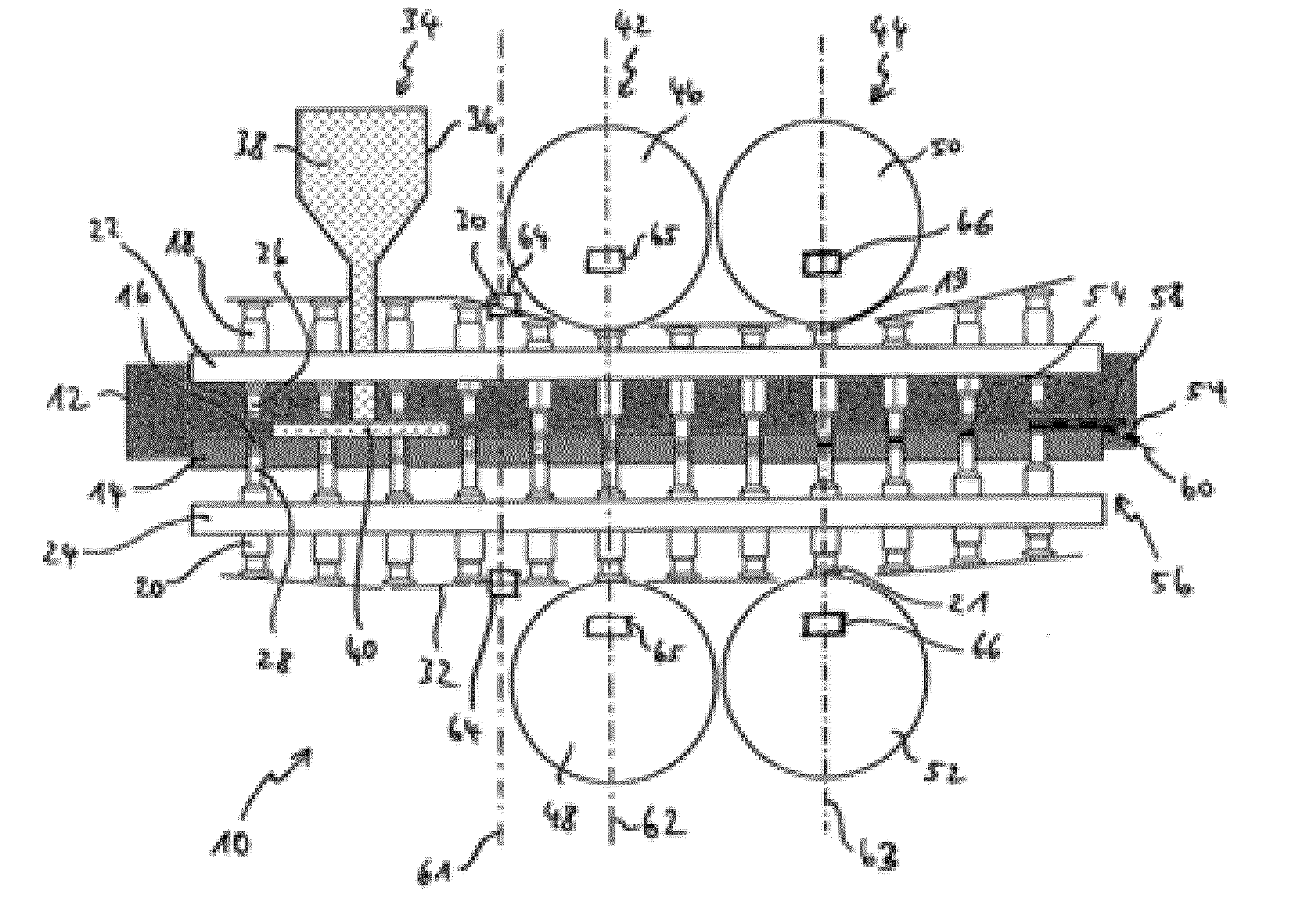
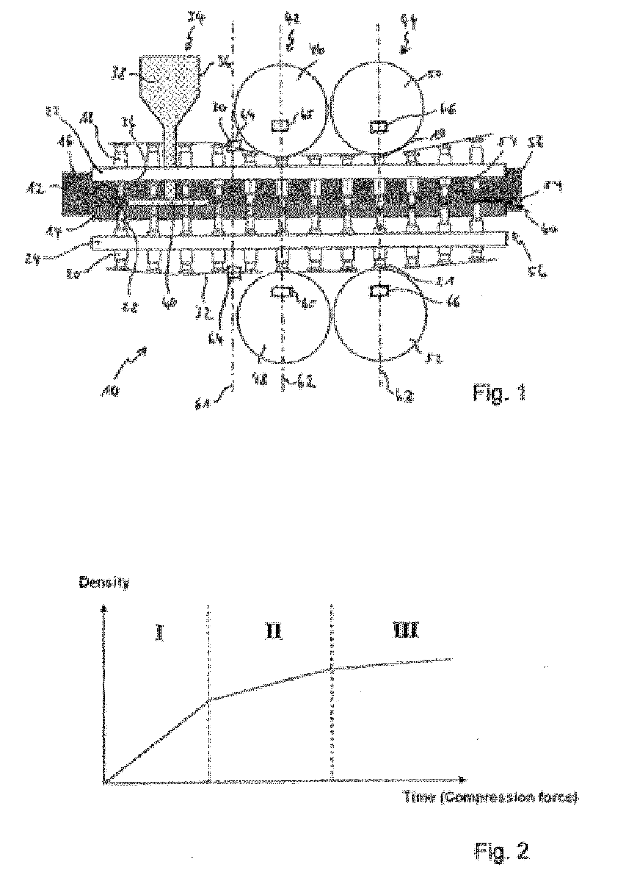
[0024]In the figures, the same reference numbers refer to the same objects unless indicated otherwise. In FIG. 1, parts of a tablet press 10 according to the invention are shown with a straightened rotor for the purposes of illustration. The schematically represented rotor 12 comprises a die plate 14 having a plurality of die holes 16. A pair, comprised of an upper punch 18 and a lower punch 20, which are respectively guided in an upper guide disk 22 and a lower guide disk 24, is assigned to each of the die holes 16 and rotate synchronously with the die plate 14. The upper and lower punches 18, 20 are disposed in such a way that they can be guided with their respective pressin...


PUM

PropertyMeasurementUnit
vibration frequenciesaaaaaaaaaa
axial movementaaaaaaaaaa
areaaaaaaaaaaa

Abstract

The invention relates to a rotary tablet press comprising: a rotatingly drivable rotor, having a die plate comprising die holes and assigned to the die holes upper and lower punches, rotating synchronously with the die plate, whose axial movement is controlled by upper and lower control cams, having at least one filling station comprising at least one filling device for filling the die holes with material to be pressed, having at least one compression station disposed downstream of the filling station in the rotational direction of the rotor, comprising at least one pressing device which presses the upper and/or lower punches into the die holes when passing through the compression station in order to press the filled material in the die holes, and having at least one ejector station, disposed downstream of the compression station in the rotational direction of the rotor, comprising an ejector device for ejecting the pressed tablets in the die holes, characterized in that at least one vibration generator is provided in the circumferential direction of the upper and lower punches between the filling station and the ejector station that at least temporarily vibrates the upper and/or lower punches at least at the compression station and/or at the filling station and/or at least at an upper control cam and/or at least at a lower control cam.

Description

CROSS-REFERENCE TO RELATED APPLICATIONS[0001]Not applicable.STATEMENT REGARDING FEDERALLY SPONSORED RESEARCH[0002]Not applicable.BACKGROUND OF THE INVENTION[0003]The invention relates to a rotary tablet press comprising a rotatingly drivable rotor, having a die plate comprising die holes and assigned to the die holes upper and lower punches, rotating synchronously with the die plate, whose axial movement is controlled by upper and lower control cams, having at least one filling station comprising at least one filling device for filling the die holes with material to be compressed, having at least one compression station disposed downstream of the filling station in the rotational direction of the rotor, comprising at least one compression device which presses the upper and / or lower punches into the die holes when passing through the compression station in order to press the filled material in the die holes, and having at least one ejector station, disposed downstream of the compress...

Claims


Application Information

Patent Timeline
Patent Type & Authority Applications(United States)
IPC IPC(8): B28B1/08B29C43/56
CPCB30B11/08B30B11/022B29C43/006B29L2031/00
Inventor HEINRICH, THOMASSCHMIDT, INGONAEVE, JAN
Owner FETTE COMPACTING GMBH
Why Eureka
Try Eureka