
Motor

a technology of motors and magnets, applied in the direction of motor/generator/converter stoppers, dynamo-electric converter control, instruments, etc., can solve the problems of poor magnetic detection accuracy, poor reliability, and easy cracking or breakage of magnets, so as to improve accuracy and reliably detect the magnetic change of sensor magnets

Active Publication Date: 2011-07-28
NIPPON DENSAN CORP
View PDF52 Cites 62 Cited by
  • Summary
  • Abstract
  • Description
  • Claims
  • Application Information

AI Technical Summary

Benefits of technology

[0008]Preferred embodiments of the present invention provide a motor which is simple in structure, capable of reliably fixing a sensor magnet against movement relative to the rotation axis of a shaft and capable of enabling a sensor to reliably detect a magnetic change of the sensor magnet with increased accuracy.
[0010]With the motor according to a preferred embodiment of the present invention, it is possible to securely fix the sensor magnet to the shaft so that the sensor magnet will not rotate about the rotation axis into a deviated position or be removed from the shaft. Moreover, the present motor enables the sensor to reliably detect the magnetic change in the sensor magnet with increased accuracy.

Problems solved by technology

However, if the magnet includes a raised portion or a recess portion formed in the magnet that is used to restrict movement of the magnet about the rotation axis of a shaft, the magnet becomes, e.g., difficult to mold and vulnerable to cracking or breakage.
This vulnerability is disadvantageous in terms of productivity and durability.
Moreover, raised portions and recessed portions may cause a change in the magnetic force of the magnet, thereby adversely affecting the detection accuracy of a sensor including the magnet.

Method used


Image

  • Motor
  • Motor
  • Motor

Examples


Embodiment Construction

[0020]Preferred embodiments of the present invention will now be described with reference to the accompanying drawings which form a part hereof. The following description of the preferred embodiments is merely for illustrative purposes and is not intended to limit the scope of the present invention and the application or use thereof.

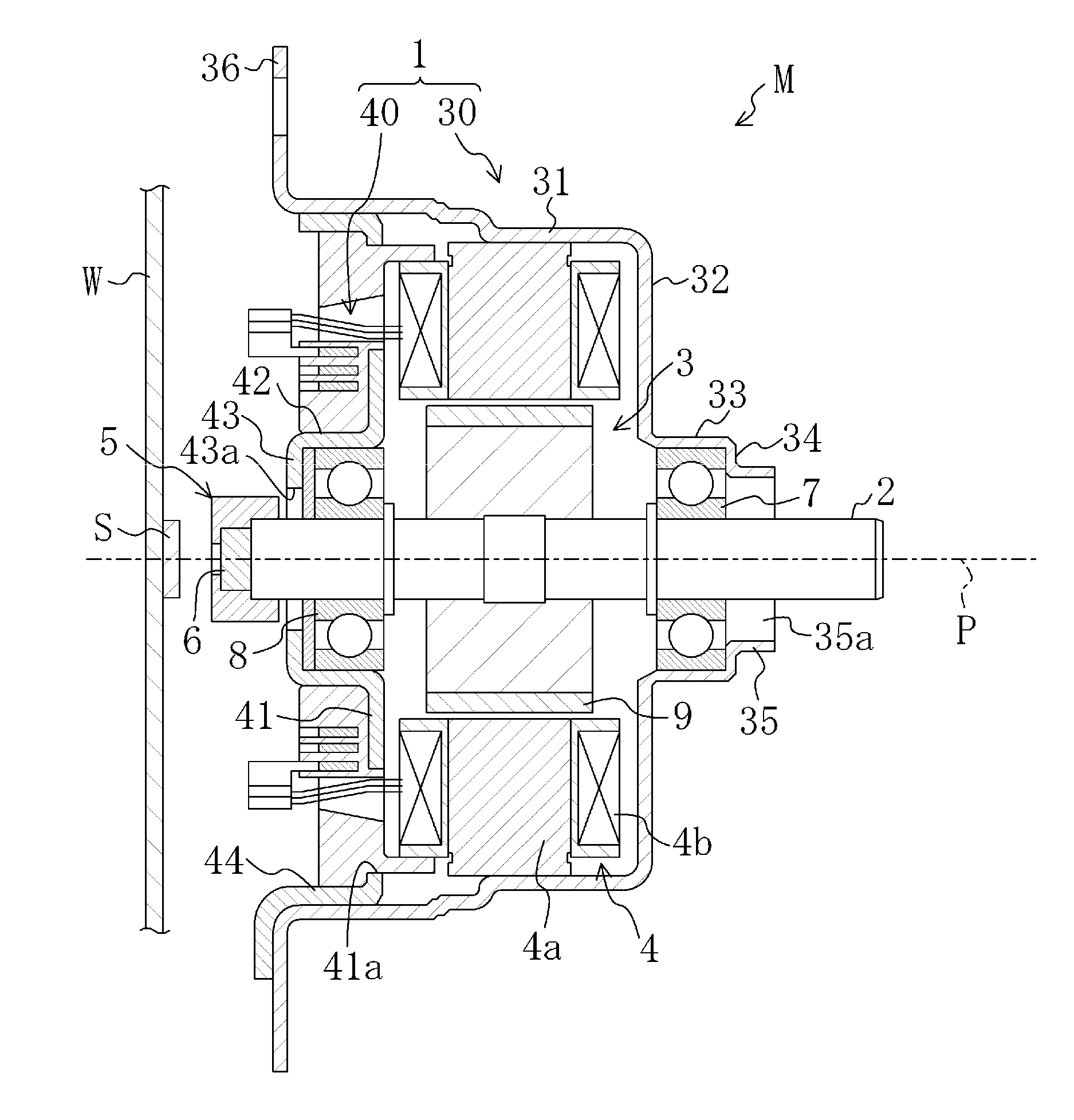
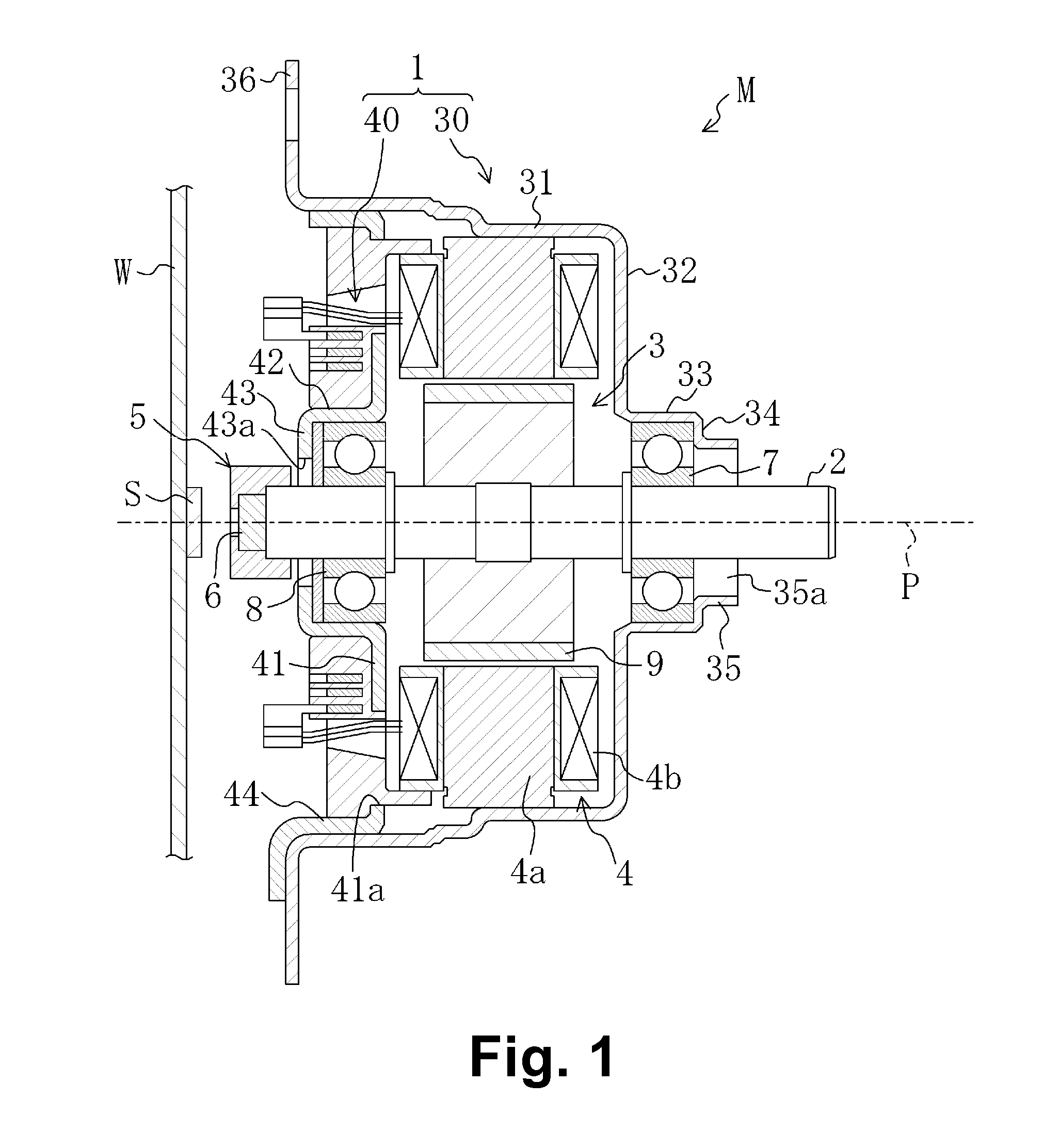
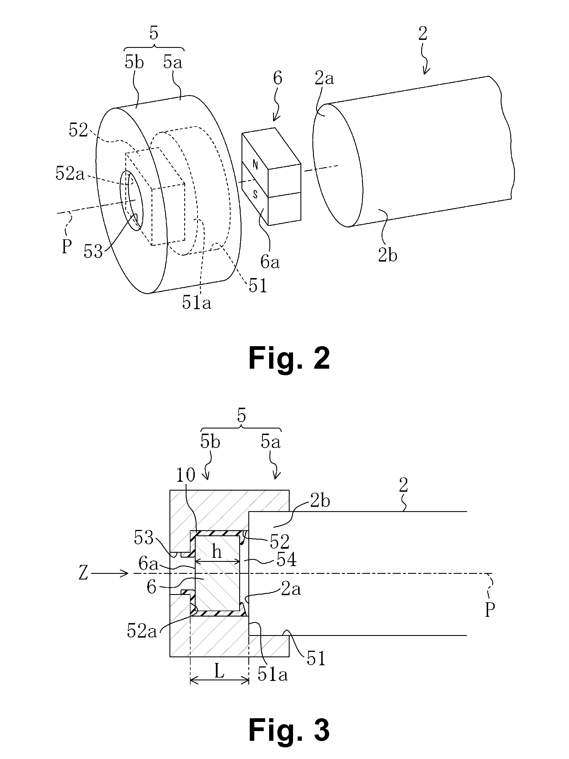
[0021]FIG. 1 is a vertical section view schematically showing a motor M according to a preferred embodiment of the present invention. The motor M may be, e.g., a motor mounted to a motor vehicle to drive a transfer case, a transmission, a power steering device, etc. The motor M preferably includes a motor housing 1, a shaft 2, a rotor 3, a stator 4, a magnet cover 5 (or a cover member) and a sensor magnet 6.

[0022]The motor housing 1 preferably includes a first housing member 30 having a case shape and a second housing member 40 having a bottom cover shape, both of which are preferably formed by pressing a steel plate, for example. However, it should be n...


PUM


Abstract

A motor includes a sensor magnet having a non-circular contour and a magnet cover fixed to an end portion of a shaft to cover the end portion of the shaft. The magnet cover includes a support portion positioned outside the end surface of the end portion of the shaft. In the support portion, a magnet hole having a non-circular cross section as the sensor magnet and extending in the direction of the rotation axis is provided. The sensor magnet is inserted into the magnet hole and fixed to the magnet hole.

Description

BACKGROUND OF THE INVENTION[0001]1. Field of the Invention[0002]The present invention relates to a motor provided with a sensor magnet at an end portion of a shaft.[0003]2. Description of the Related Art[0004]A contactless rotation angle detection device for detecting, e.g., the rotation angle of a motor, is usually of the type using, e.g., a resolver or a plurality of Hall ICs.[0005]In recent years, a rotary encoder including a magnet attached to an end surface of a shaft and a sensor provided in an opposing relationship with the magnet has been used.[0006]Japanese Patent No. 3517350 discloses a conventional example of a motor in which a magnet attached to a rotating shaft is prevented from moving about the rotating shaft through the use of a bush.[0007]However, if the magnet includes a raised portion or a recess portion formed in the magnet that is used to restrict movement of the magnet about the rotation axis of a shaft, the magnet becomes, e.g., difficult to mold and vulnerable...

Claims


Application Information

Patent Timeline
IPC IPC(8): H02K29/08
CPCH02K29/08G01D5/145H02K11/215
Inventor ASAHI, KYOHEIFURUTACHI, EIJI
Owner NIPPON DENSAN CORP
Features
  • Generate Ideas
  • Intellectual Property
  • Life Sciences
  • Materials
  • Tech Scout
  • Unparalleled Data Quality
  • Higher Quality Content
  • 60% Fewer Hallucinations
Learn More