Controller for a Power Converter and Method of Operating the Same

Active Publication Date: 2011-07-28
POWER SYST TECH
View PDF108 Cites 91 Cited by
  • Summary
  • Abstract
  • Description
  • Claims
  • Application Information

AI Technical Summary

Benefits of technology

These and other problems are generally solved or circumvented, and technical advantages are generally achieved, by advantageous embodiments of the present invention, including a controller for a power converter and method of operating the same. In one embodiment, the controller includes a primary peak current circuit configured to produce a reference voltage corresponding to a primary peak current through a primary winding of a transformer of a p

Problems solved by technology

With conventional design approaches, however, it is difficult to achieve quasi-resonant power converter operation and, at the same time, regulate an output current of the power converter.
This process may defeat quasi-resonant switching operation of the power converter.
This approach increases power converter cost due to the presence of the optocoupler.
This approach preserves quasi-resonant switching without the need for an optocoupler, but requires a complex calculation in the controller.
Thus, a controller that regulates an output current of a power converter such as a quasi-resonant flyback power converter that preserves primary-to-secondary side isolation of the power converter and efficient quasi-resonant operation still presents unresolved design challenges.

Method used


Image

  • Controller for a Power Converter and Method of Operating the Same
  • Controller for a Power Converter and Method of Operating the Same
  • Controller for a Power Converter and Method of Operating the Same

Examples


Embodiment Construction

The making and using of the present exemplary embodiments are discussed in detail below. It should be appreciated, however, that the present invention provides many applicable inventive concepts that can be embodied in a wide variety of specific contexts. The specific embodiments discussed are merely illustrative of specific ways to make and use the invention, and do not limit the scope of the invention.

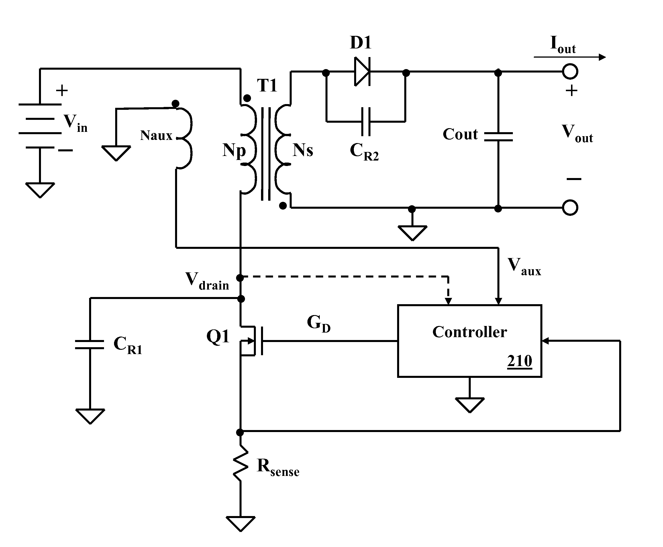
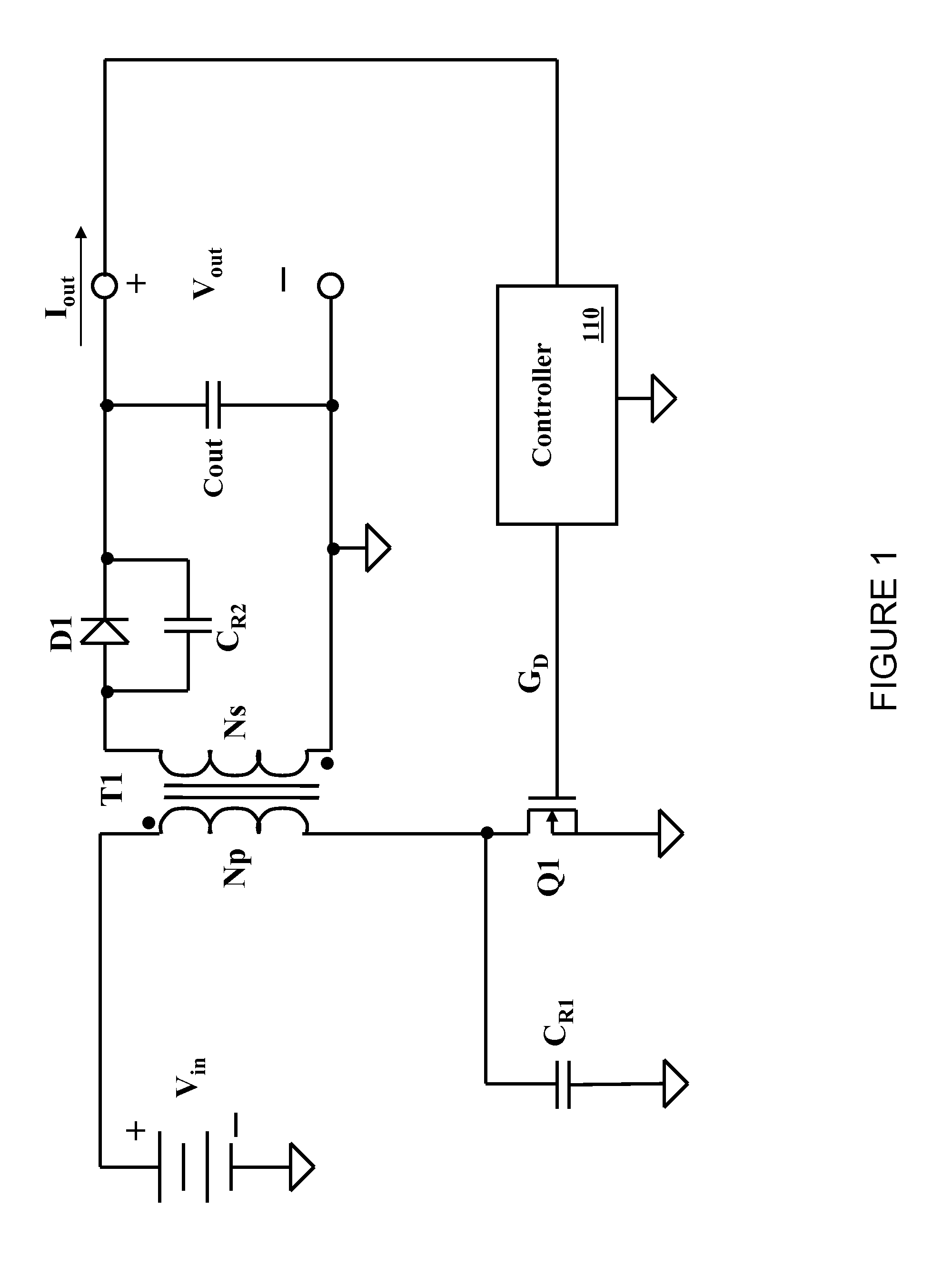
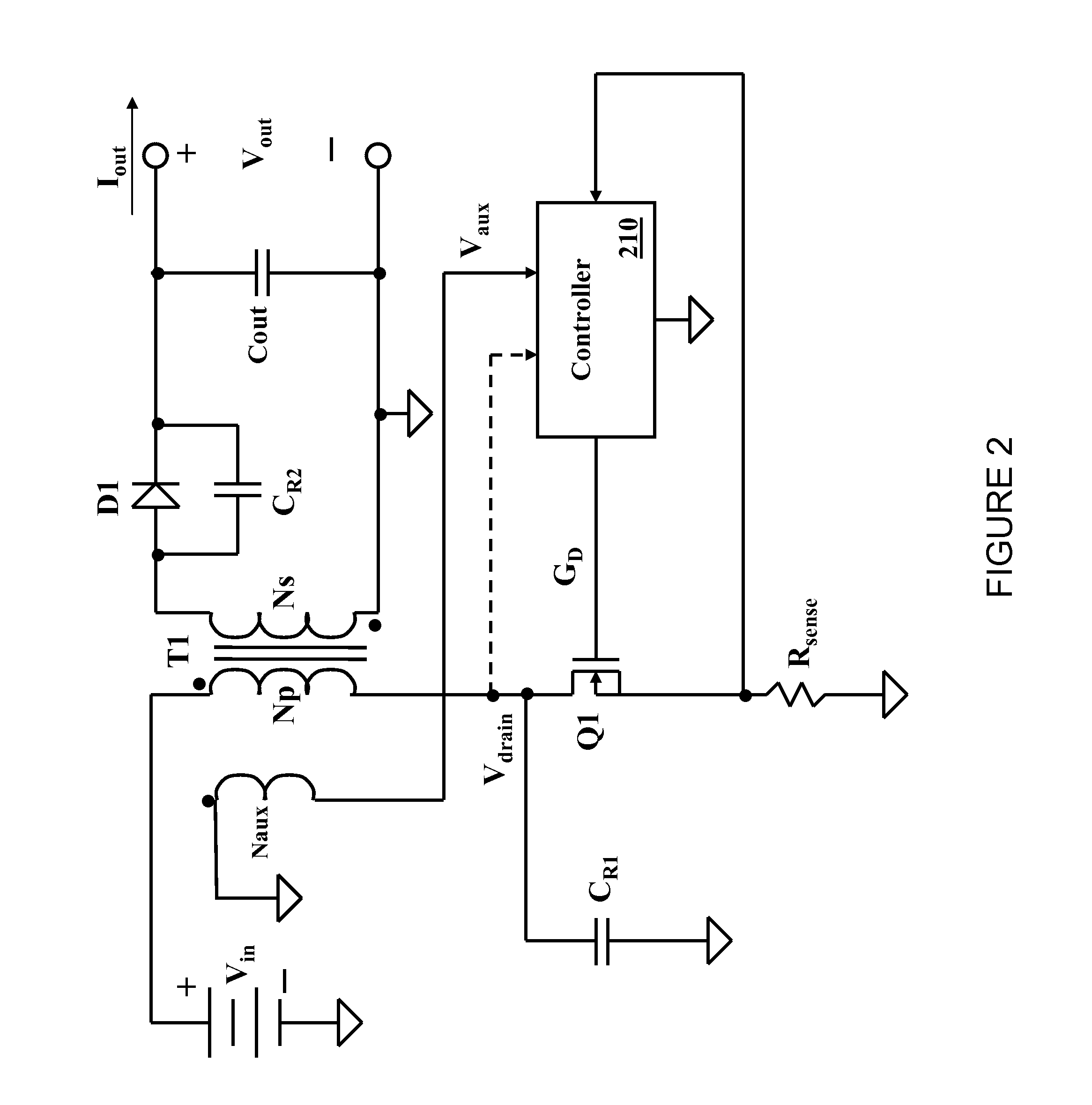
The present invention will be described with respect to exemplary embodiments in a specific context, namely, a controller for a power converter (e.g., a quasi-resonant flyback power converter) configured to control a power switch thereof by sensing signals in the power converter such as on the primary side of the power converter. While the principles of the present invention will be described in the environment of a power converter, any application that may benefit from a power converter including a motor drive or a power amplifier is well within the broad scope of the present invent...


PUM


Abstract

A controller for a power converter and method of operating the same. In one embodiment, the controller includes a primary peak current circuit configured to produce a reference voltage corresponding to a primary peak current through a primary winding of a transformer of a power converter, and an offset corrector configured to provide an offset voltage to compensate for delays in the power converter. The controller also includes a summer configured to provide an offset reference voltage as a function of the reference voltage and the offset voltage, and a comparator configured to produce a signal to turn off a power switch coupled to the primary winding of the transformer as a function of the offset reference voltage.

Description

TECHNICAL FIELDThe present invention is directed, in general, to power electronics and, more specifically, to a controller for a power converter and method of operating the same.BACKGROUNDA switched-mode power converter (also referred to as a “power converter” or “regulator”) is a power supply or power processing circuit that converts an input voltage waveform into a specified output voltage waveform. DC-DC power converters convert a direct current (“dc”) input voltage that may be derived from an alternating current (“ac”) source by rectification into a dc output voltage. Controllers associated with the power converters manage an operation thereof by controlling conduction periods of power switches employed therein. Some power converters include a controller coupled between an input and output of the power converter in a feedback loop configuration (also referred to as a “control loop” or “closed control loop”) to regulate an output characteristic of the power converter.Typically, t...

Claims


Application Information

Patent Timeline
IPC IPC(8): H02M3/335
CPCY02B70/1433H02M3/33507Y02B70/10
Inventor GENANNT BERGHEGGER, RALF SCHROEDER
Owner POWER SYST TECH
Why Eureka
Try Eureka