
Thermal detector, thermal detecting device, and electronic instrument

a technology of thermal detection and electronic instruments, applied in the direction of instruments, heat measurement, optical radiation measurement, etc., can solve the problems of difficult to form the shape of a step-shaped change or an undercut in a cross-sectional view, the support arm will not have sufficient strength, and the light capture efficiency to decline, etc., to achieve the effect of easy to achiev

Active Publication Date: 2011-07-28
SEIKO EPSON CORP
View PDF21 Cites 6 Cited by
  • Summary
  • Abstract
  • Description
  • Claims
  • Application Information

AI Technical Summary

Benefits of technology

[0008]Changing the shape of an outer contour (outline) in a plan view can be accomplished easily using photolithographic patterning, which is a conventional technique used in semiconductor manufacturing. However, even if a sacrificial layer is fabricated for forming the hollow section and isotropic etching is used to form the support arm, it is difficult to form the shape of a step-shaped change or an undercut in a cross sectional view as shown in Japanese Laid-Open Patent Publication No. 2007-71885 and an increased number of manufacturing steps is required to mask only the portion where the support arm will be formed and execute the isotropic etching.
[0009]Additionally, from the perspective of forming wiring (a conductor) on the support arm connecting to the thermal detecting element, there has been a need to improve the support arm in relation to dissipation of heat conducted through the wiring, breakage of wiring, ensuring sufficient strength, and heat transfer.
[0010]With several aspects of the present invention, it is possible to provide a thermal detector, a thermal detecting device, and an electronic instrument in which a strength of an arm is increased, heat dissipation from the arm is decreased, and breakage of wiring in the arm can be prevented.

Problems solved by technology

However, the support arm will not have sufficient strength if it is too narrow.
If the strength is insufficient, then the support member may adhere and become stuck (sticking) to a bottom surface of the hollow section during manufacturing or the orientation of the detection element may change during use and cause a light capturing efficiency to decline.
However, even if a sacrificial layer is fabricated for forming the hollow section and isotropic etching is used to form the support arm, it is difficult to form the shape of a step-shaped change or an undercut in a cross sectional view as shown in Japanese Laid-Open Patent Publication No. 2007-71885 and an increased number of manufacturing steps is required to mask only the portion where the support arm will be formed and execute the isotropic etching.
Furthermore, when the arms extend and contract due to, for example, temperature changes, moments develop which tend to cause the mounting member to rotate in opposite directions in a plan view.

Method used


Image

  • Thermal detector, thermal detecting device, and electronic instrument
  • Thermal detector, thermal detecting device, and electronic instrument
  • Thermal detector, thermal detecting device, and electronic instrument

Examples


first embodiment

1. First Embodiment

1.1. Overall Structure of Infrared Detector

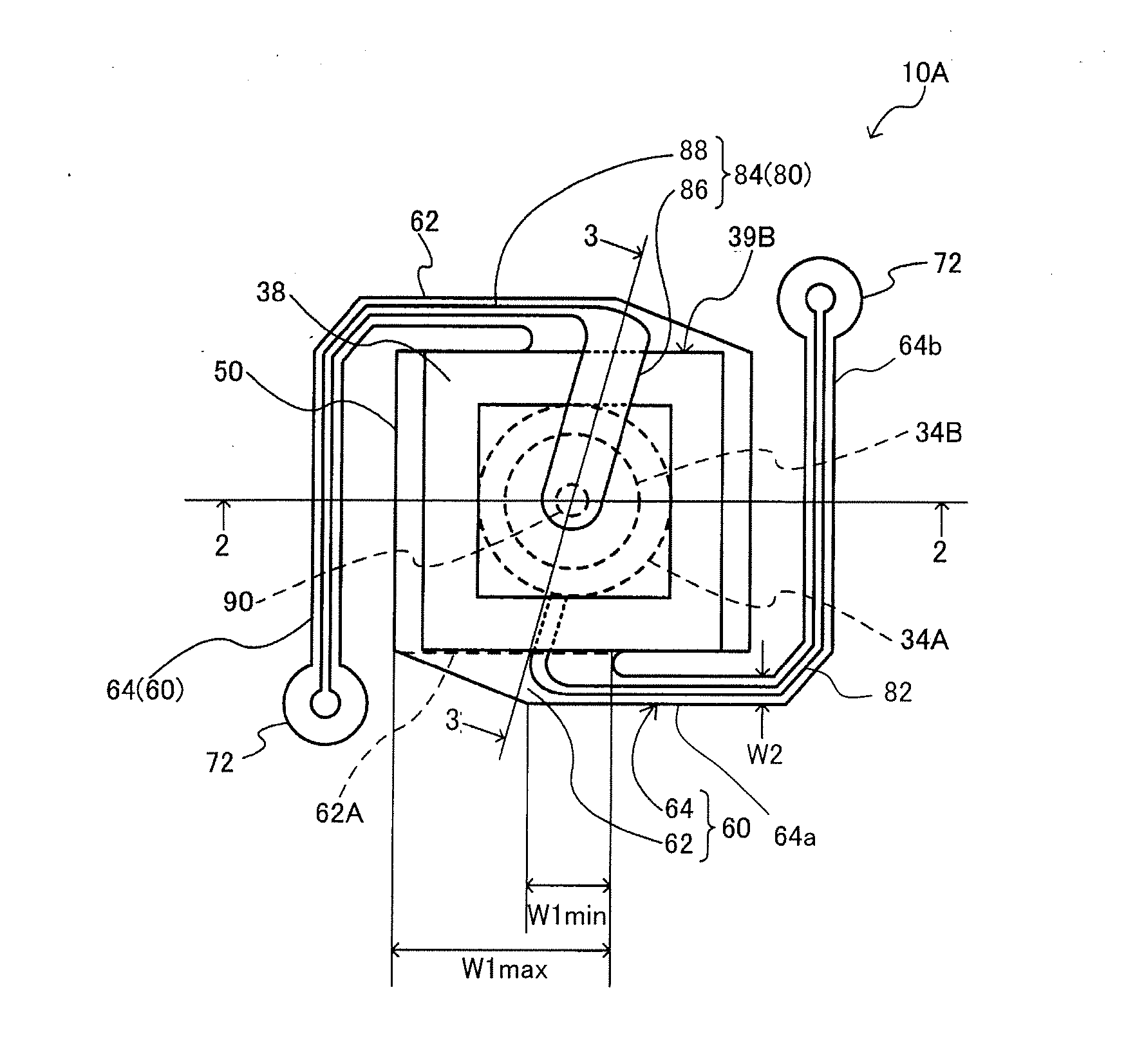
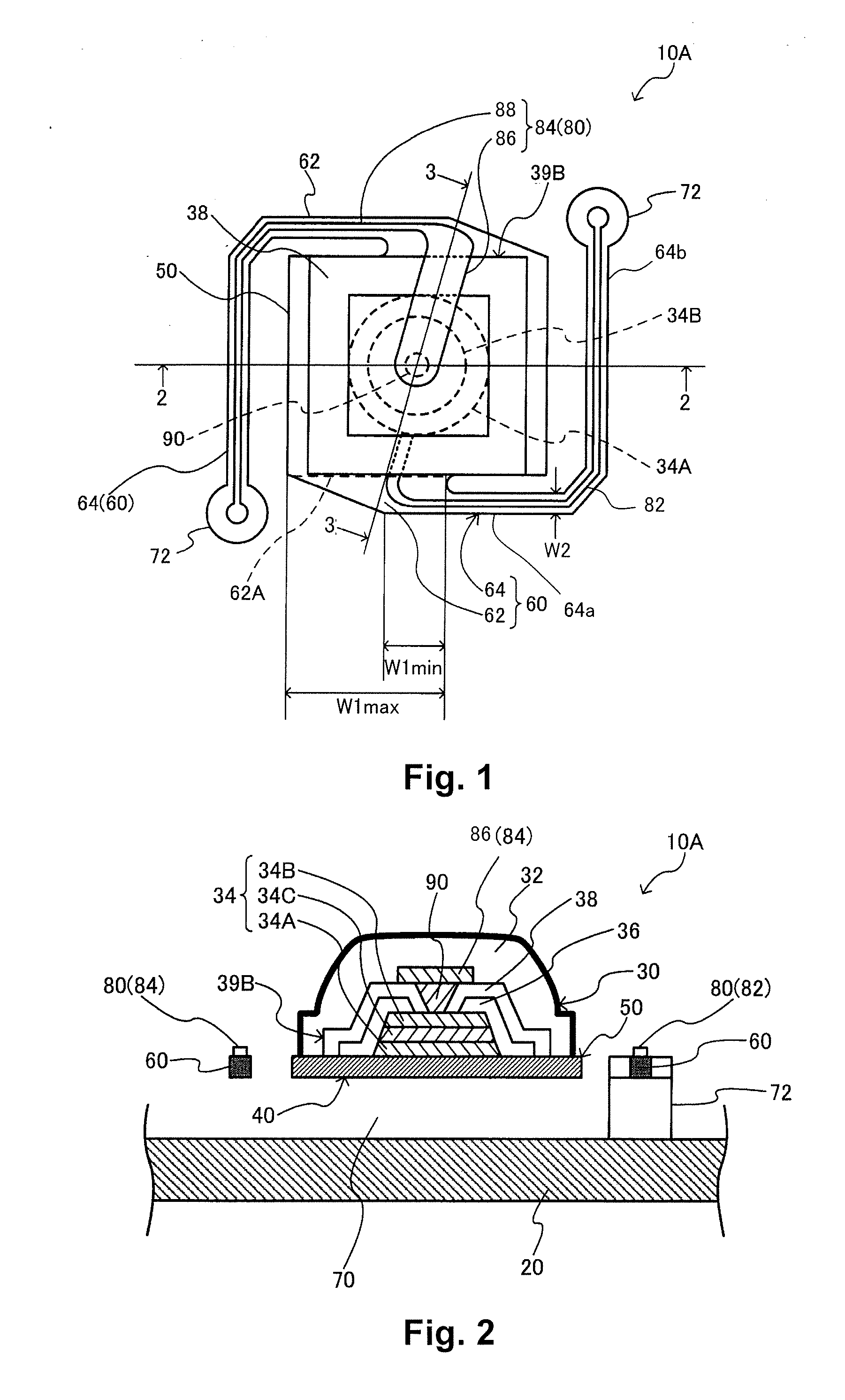
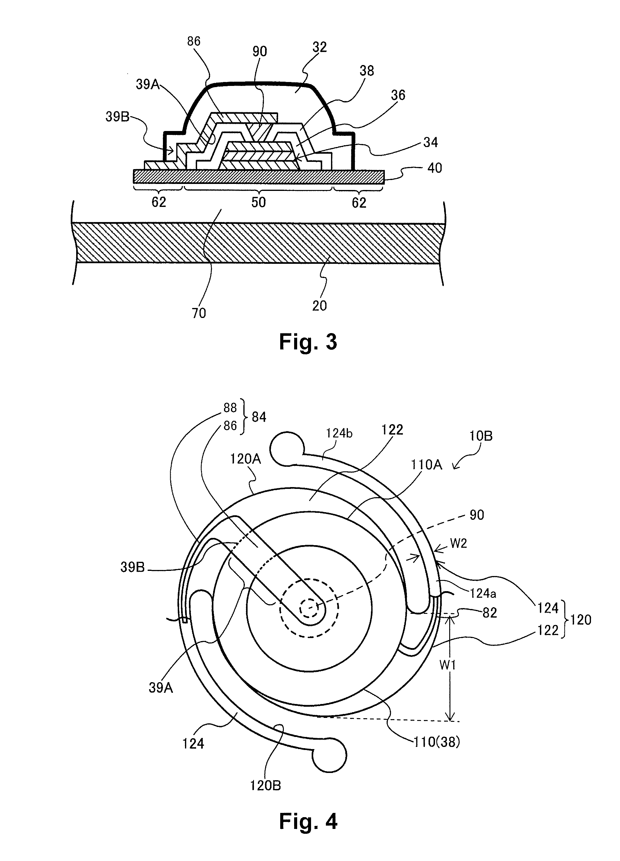
[0042]FIG. 1 is a plan view of an infrared detector according to a first embodiment of a thermal detector according to the present invention and shows a planar layout of a support member and wiring. FIG. 2 is a cross sectional view taken along a section line 2-2 of FIG. 1. The infrared detector 10A corresponds to one cell and a plurality of such one-cell infrared detectors 10A arranged on a substrate in a two-dimensional arrange along directions parallel to two perpendicular axes can constitute an infrared detecting device.

[0043]As shown in FIGS. 1 and 2, the infrared detector 10a includes a substrate 20, an infrared detecting element (one example of a thermal detecting element) 30 that includes an infrared absorbing film (one example of a light absorbing film) 32, and a support member (membrane) 40 that supports the infrared detecting element 30. The substrate 20 and the support member 40 are thermally isolated from each...

second embodiment

2. Second Embodiment

[0065]FIG. 4 is a plan view showing a planar layout of a support member and wiring of an infrared detector 10B according to a second embodiment of the present invention. The details of the substrate 20 and the infrared detecting element 30 are omitted in FIG. 4, but the structure is the same as the first embodiment except that the outline of the infrared detector 10B is circular.

[0066]As shown in FIG. 4, a support member 100 includes a mounting member 110 and two arms 120. Each of the arms 120 includes an arm base end section 122 and an arm body section 124. The two arms 120 are positioned such that the arm base end sections 122 are point-symmetrical about a center of the mounting member 110. The arm base end section 122 extends outwardly from the mounting member 110 toward a first direction and the arm base section 122 has a first width W1 measured along a direction perpendicular to the first direction as shown in FIG. 4. The arm body section 124 has a proximal ...

third embodiment

3. Third Embodiment

[0073]FIG. 5 is a plan view showing a planar layout of a support member and wiring of an infrared detector 10C according to a third embodiment of the present invention. The details of the infrared detecting element 30 are omitted in FIG. 5, but the structure is the same as the first embodiment except that the outline of the infrared detector 10C is circular.

[0074]As shown in FIG. 5, a support member 200 includes a mounting member 210 and two arms 220. Each of the arms 220 includes an arm base end section 222 and an arm body section 224. The two arms 220 are positioned such that the arm base end sections 222 are point-symmetrical about a center of the mounting member 210. As shown in FIG. 5, the arm body section 224 has a proximal end portion 224a extending from the arm base end section 222 generally along an outer contour of the mounting member 210 with the proximal end portion 224a being spaced apart from an edge of the mounting member 210 in the first direction....


PUM

PropertyMeasurementUnit
surface areaaaaaaaaaaa
widthaaaaaaaaaa
pyroelectricaaaaaaaaaa

Abstract

A thermal detector includes a thermal detecting element and a support member supporting the thermal detecting element and a wiring layer. The support member has an arm member connected to a mounting member with the first arm member having an arm base end section extending outwardly from the mounting member toward a first direction, the arm base section having a first width measured along a direction perpendicular to the first direction, and an arm body section having a proximal end portion extending from the arm base end section generally along an outer contour of the mounting member with the proximal end portion being spaced apart from an edge of the mounting member in the first direction. The proximal end portion of the arm body section has a second width measured along a direction perpendicular to a lengthwise direction of the arm body section that is narrower than the first width.

Description

CROSS-REFERENCE TO RELATED APPLICATIONS[0001]This application claims priority to Japanese Patent Application No. 2010-014670 filed on Jan. 26, 2010. The entire disclosure of Japanese Patent Application No. 2010-014670 is hereby incorporated herein by reference.BACKGROUND[0002]1. Technical Field[0003]The present invention relates to an infrared detector or other thermal detector, a thermal detecting device, and an electronic instrument.[0004]2. Related Art[0005]A known type of thermal detecting device is a pyroelectric or bolometric infrared detection device. The infrared detection device detects infrared radiation by absorbing heat in the form of infrared radiation with an infrared absorbing film and detecting an electromotive force generated (pyroelectric) or a change of a resistance value (bolometric) in a thermal infrared detection element. The infrared detection element is supported by a support member and a hollow section is formed between the support member and a substrate for...

Claims


Application Information

Patent Timeline
Patent Type & Authority Applications(United States)
IPC IPC(8): G01K1/14G01J5/00
CPCG01J5/02G01J5/34G01J5/20G01J5/023G01J5/12
Inventor KAMIKAWA, TAKETOMI
Owner SEIKO EPSON CORP
Learn More