
Methods and Systems for Image Noise Filtering

a filtering and noise technology, applied in the field of methods and systems for filtering noise, can solve the problems of degrading image quality, noise may adversely affect the output quality of image processing tasks performed, and the bayer domain

Active Publication Date: 2011-07-28
TEXAS INSTR INC
View PDF10 Cites 19 Cited by
  • Summary
  • Abstract
  • Description
  • Claims
  • Application Information

AI Technical Summary

Benefits of technology

The invention provides methods and systems for image noise filtering in digital systems that capture digital images. The invention uses a noise filter with small support to remove low-frequency noise without losing high-frequency parts of the image. The invention also applies the noise filter in the Bayer domain to suppress strong chrominance noise without destroying luminance detail. The invention can be implemented in a digital camera or other digital systems. The technical effects of the invention include improved image quality and reduced noise in captured images.

Problems solved by technology

Images (i.e., single photographs or frames / pictures in video sequences) captured by imaging sensors in digital cameras often contain large amounts of random noise, especially in low-light conditions, that degrades image quality.
For example, the noise may adversely affect the quality of the output of image processing tasks performed in the Bayer domain, such as color correction and demosaicing.
Low frequency spatial noise may severely affect image quality, especially in the chroma channel.
However, this type of filter is expensive to implement.
This approach is effective for reducing low-frequency noise but when the filtered image is upsampled to the original resolution, the high frequency part of the image is lost.
Further, if this approach is used in the chroma channel, color-bleeding artifacts may occur in the image.
However, this approach is computationally expensive.
If a strong noise filter is applied, the strong chrominance noise is reduced but luminance detail is lost.

Method used


Image

  • Methods and Systems for Image Noise Filtering
  • Methods and Systems for Image Noise Filtering
  • Methods and Systems for Image Noise Filtering

Examples


Embodiment Construction

[0010]Specific embodiments of the invention will now be described in detail with reference to the accompanying figures. Like elements in the various figures are denoted by like reference numerals for consistency.

[0011]Certain terms are used throughout the following description and the claims to refer to particular system components. As one skilled in the art will appreciate, components in digital systems may be referred to by different names and / or may be combined in ways not shown herein without departing from the described functionality. This document does not intend to distinguish between components that differ in name but not function. In the following discussion and in the claims, the terms “including” and “comprising” are used in an open-ended fashion, and thus should be interpreted to mean “including, but not limited to . . . .” Also, the term “couple” and derivatives thereof are intended to mean an indirect, direct, optical, and / or wireless connection. Thus, if a first devic...


PUM


Abstract

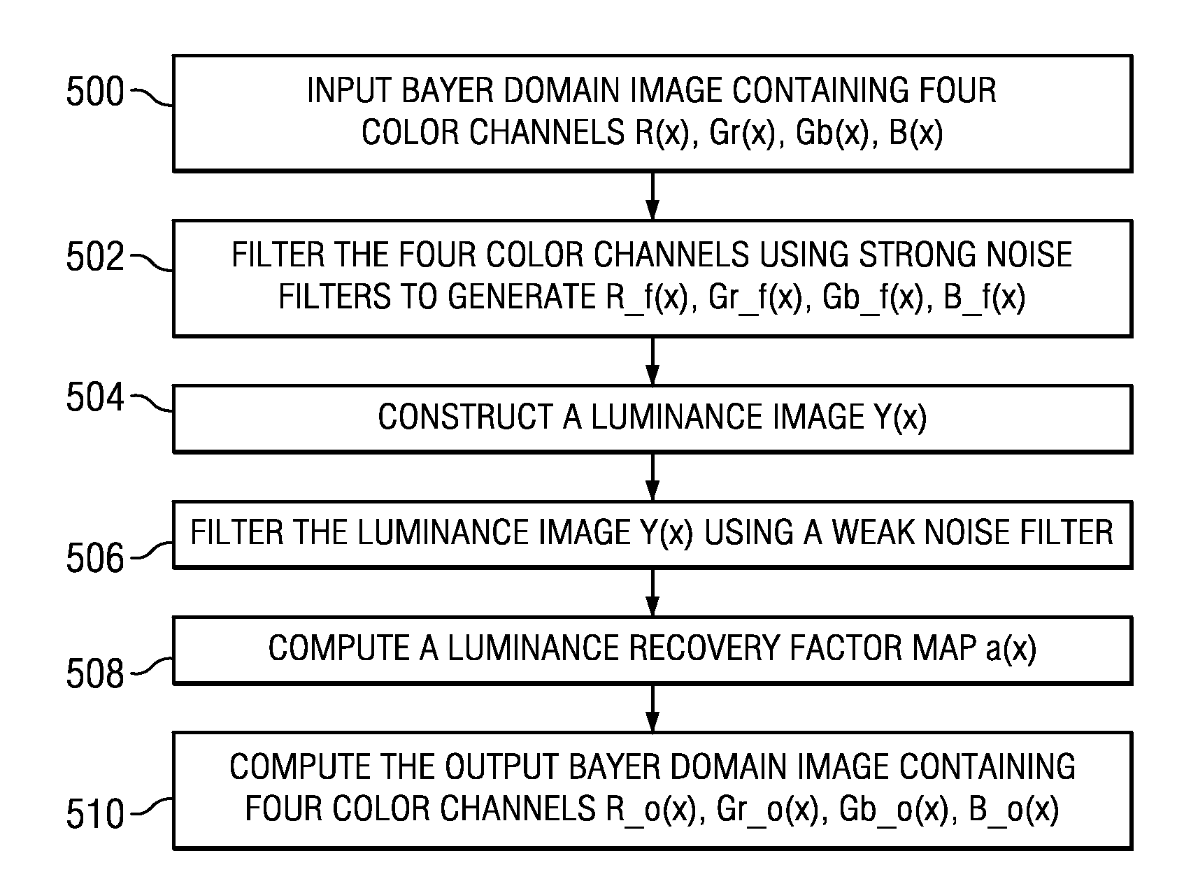
Methods and systems for image noise filtering are provided. One method of image noise filtering includes generating a plurality of sub-images of a digital image, applying a noise filter with small support to each sub-image, and generating a filtered digital image by merging the filtered sub-images. Another method of image noise filtering includes receiving a digital image including a plurality of color channels in the Bayer domain, applying a strong noise filter to each color channel to generate filtered color channels, computing a luminance image from the digital image, applying a weak noise filter to the luminance image to generate a filtered luminance image, computing a luminance recovery factor map using the luminance image and the filtered luminance image, and computing output color channels of the digital image using the filtered color channels and the luminance recovery factor map.

Description

BACKGROUND OF THE INVENTION[0001]Images (i.e., single photographs or frames / pictures in video sequences) captured by imaging sensors in digital cameras often contain large amounts of random noise, especially in low-light conditions, that degrades image quality. For example, the noise may adversely affect the quality of the output of image processing tasks performed in the Bayer domain, such as color correction and demosaicing. In another example, as imaging sensor technology improves, the resolution of the captured images increases. When the resolution increases, the pixel size becomes smaller and the spatial frequency of the noise in the captured images becomes lower. Low frequency spatial noise may severely affect image quality, especially in the chroma channel.[0002]Typically, one or more image noise filters are applied to the captured images at various points (e.g., in the Bayer domain and / or the color space domain (e.g., YCbCr or YUV)) during the processing of the images to red...

Claims


Application Information

Patent Timeline
Patent Type & Authority Applications(United States)
IPC IPC(8): G06K9/40G06K9/36
CPCG06T3/4015G06T5/002G06T2207/20221G06T2207/10004G06T2207/10024G06T5/50G06T5/70
Inventor HONG, WEI
Owner TEXAS INSTR INC
Learn More