Optical Apparatus

a technology of optical equipment and optical tubes, applied in the direction of electrical equipment, multi-station single light source, fibre transmission, etc., can solve the problem of high production cos

Inactive Publication Date: 2011-07-28
TELEFON AB LM ERICSSON (PUBL)
View PDF20 Cites 13 Cited by
  • Summary
  • Abstract
  • Description
  • Claims
  • Application Information

AI Technical Summary

Benefits of technology

[0007]By producing a second continuous wave (CW) optical signal having a predefined wavelength from a first CW optical signal received from the network which has a different wavelength, and then modulating the second CW optical signal with data (e.g. before sending the modulated signal across the network), it is possible to send the data signal back along the same fibre that the first CW signal was received from without cross talk. Further, the colour (i.e. the wavelength of the second CW optical signal) of the optical apparatus can be set by choosing the wavelength of the first CW optical signal. Making the optical apparatus colorless in this way, with the color or wavelength being set by the first CW optical signal supplied to the optical apparatus across the network, means many substantially identical apparatuses may be provided on a single WDM network, reducing costs compared with prior apparatus that are coloured (have a predefined wavelength of operation defined by the apparatus).
[0010]The first modulator may be arranged to be polarisation insensitive and may also be arranged to work over the entire range of possible wavelengths that belong to the network grid. This last feature is useful because it allows the same optical apparatus to be given to any user whilst allowing a lot of freedom in the choice of wavelength of first CW optical signal that it is supplied with.
[0014]The first filter may comprise a first optical de-interleaver. The first optical de-interleaver may be configured to deinterleave an input comb that comprises wavelengths that are twice the distance apart in the optical spectrum that the first CW signal is spaced apart from the desired second CW signal wavelength. In the case of the 50 GHz grid with a first CW signal 25 GHz from the grid the first deinterleaver should deinterleave a 50 GHz comb. The result will be two wavelength output signal—one containing the first CW signal and the other the sidebands. The first CW signal can thus be effectively filtered out from the sidebands. The ONT may drop the output signal containing the first CW signal.
[0017]The second filter may comprise an optical de-interleaver. The use of the deinterleavers is preferred because it is possible to preserve the polarisation of the first CW signal in forming the second CW signal.

Problems solved by technology

Unfortunately, this means that, historically, the optical apparatus provided for each user at their optical network termination has to be slightly different from that of each other user to enable the apparatus to transmit a signal at its unique allocated wavelength.
In practice this means that each piece of user optical apparatus has to include unique and / or complex componentry, making production costs high.

Method used


Image

  • Optical Apparatus
  • Optical Apparatus
  • Optical Apparatus

Examples


Embodiment Construction

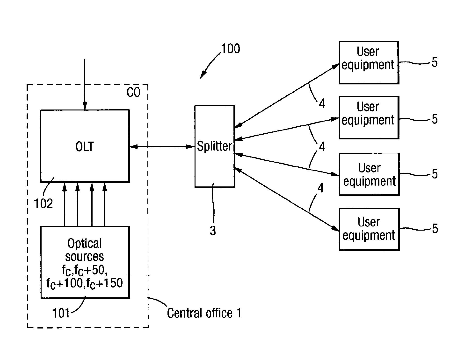
[0040]In FIG. 1, a four user optical communication access network which operates in accordance with the 50 GHz ITU-grid standard is shown. Embodiment of the invention may, of course, have application to other kinds of optical network or in accordance with other standards that define operating wavelength, but it is envisaged that in at least this arrangement it may have application to a 50 GHz network.

[0041]The network 100 comprises a central office (CO) and an optical line terminal (OLT) 102. The OLT 102 is connected through a single optical fibre 2 to a passive splitter 3. The splitter 3 connects the fibre 2 to a set of fibres 4 (here, four fibre, although more could be provided). Each of the fibres 4 is connected to a respective optical apparatus 5. Each apparatus 5 is associated with a respective user. Typically the optical apparatus will be located at the users premises or close to their premises. In the case of ITU-grid networks each optical apparatus may form part or all of an...


PUM


Abstract

An optical apparatus for use in an optical communications network, and a method of operating a network are described. The apparatus includes an input suitable for receiving a first continuous wave optical signal from a remote location on a network, and a modifying unit arranged to modify the first continuous wave optical signal to produce a second continuous wave optical signal having a wavelength which is different from the wavelength of the first continuous wave optical signal. A modulating unit is arranged to modulate the second continuous wave optical signal with data to produce a modulated second continuous wave optical signal.

Description

TECHNICAL FIELD[0001]This invention relates to improvements in optical apparatus for use in an optical communication networks.BACKGROUND[0002]In an optical network, such as a Passive Optical access Network, each user is provided with their own optical apparatus. Information is sent to each user's optical apparatus from a piece of equipment on the network such as an optical line terminal OLT. The OLT may be connected to each user's apparatus through a single fibre and an optical distribution node, which is typically a passive splitter in a conventional Passive optical network (PON) or a wavelength selective splitter in a wavelength division multiplexing (WDM) PON. The role of the user's optical apparatus is to send an optical signal—which the user can modulate with data—across the network for transmission to other equipment on the network. It will typically send that information to a central office. The user apparatus may also function to read optical information sent to it from the ...

Claims


Application Information

Patent Timeline
Patent Type & Authority Applications(United States)
IPC IPC(8): H04J14/00H04B10/2587
CPCH04B10/2587
Inventor CAVALIERE, FABIO
Owner TELEFON AB LM ERICSSON (PUBL)
Why Eureka
Try Eureka