
Battery arrays, constructions and method

Inactive Publication Date: 2011-07-28
CYMBET CORP
View PDF25 Cites 166 Cited by
  • Summary
  • Abstract
  • Description
  • Claims
  • Application Information

AI Technical Summary

Benefits of technology

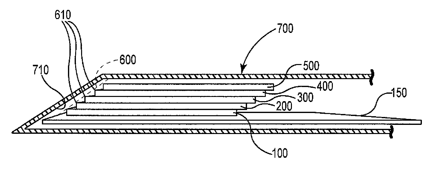
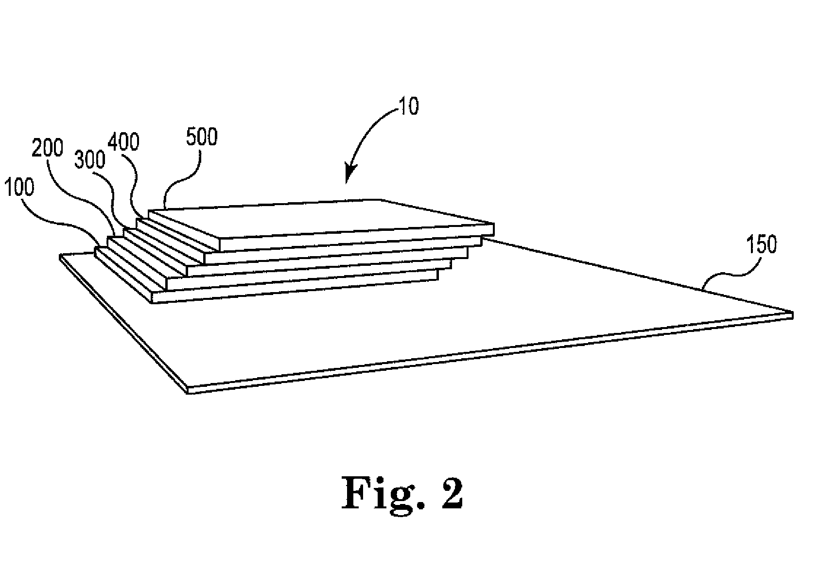
[0012]The present invention advantageously provides in one embodiment a stacked array of batteries so that the battery array has a specialized shape, but is fabricated using individual batteries that can be readily mass produced. In another embodiment, the array of batteries is arranged in a manner to provide excellent efficiencies in use of space, while at the same time using individual batteries that can be readily mass produced. Thus, the present product can in one aspect provide the advantages of economies of scale through readily manufactured individual battery components, while at the same time providing uniquely shaped battery arrays suitable for custom applications on a relatively small scale. The present invention therefore provides efficiencies not available using conventional single battery cell custom shape manufacture technology.
[0013]A thin film battery is also provided wherein at least one via is provided through the substrate and at least one other via through an insulation layer to provide electronic connection to the battery cell. This battery configuration affords particular advantage in providing a battery that can be connected to a device having unique configuration requirements, and optionally providing an opportunity to avoid use of a separate package for containment of the battery. Additionally, the unique connection points of contacts for the battery enables alternative connection configurations of multiple batteries to be connected either in series or in parallel.

Problems solved by technology

One drawback to such portable devices is the need to include the power supply with the device.
Sufficient battery capacity can result in a power supply that is disproportionately heavy and / or large compared to the device.
However, due at least in part to the relatively small size, such storage devices may not be able to provide adequate power for an associated electronic device.
Such configurations, though, require multiple batteries and space in a small, portable device once again becomes an issue.

Method used


Image

  • Battery arrays, constructions and method
  • Battery arrays, constructions and method
  • Battery arrays, constructions and method

Examples


Embodiment Construction

[0033]It is to be understood that a device and method in accordance with the present invention includes, but is not limited to, novel combinations of conventional components, and not just particular detailed configurations thereof. Accordingly, the structure, methods functions, control and arrangement of conventional components and circuits have, for the most part, been illustrated in the drawings by readily understandable block representations and schematic diagrams, in order not to obscure the disclosure with structural details which will be readily apparent to those skilled in the art, having the benefit of the description herein. Further, the invention is not limited to the particular embodiments depicted in the exemplary diagrams, but should be construed in accordance with the language in the claims.

[0034]In accordance with the present invention, multiple batteries of relatively small dimension, and having relatively flat form factor may be arranged inside a relatively small el...


PUM

PropertyMeasurementUnit
Sizeaaaaaaaaaa
Volumeaaaaaaaaaa
Shapeaaaaaaaaaa

Abstract

Disclosed is a stacked array of a plurality of thin film batteries that are electrically connected together. The stacked array is in a staggered configuration. The outermost points of side edges on one side of the stacked array preferably generally conform to an interior surface of an electronic device or component thereof in order to advantageously save space in the device. In an embodiment, the stacked array comprises at least one battery having a single surface in contact with a plurality of batteries. In another embodiment, a shaped array of a plurality of thin film batteries electrically connected together is provided, whereby a plurality of batteries are arranged in a single layer on a non-rectangular substrate adjacent to one another generally in the shape of the surface of the substrate. Additionally, a thin film battery is described wherein at least one via is provided through the substrate and at least one other via through an insulation layer to provide electronic connection to the battery cell.

Description

REFERENCE TO RELATED APPLICATIONS[0001]This application claims the benefit of priority under 35 U.S.C. 119(e)(1) of a provisional patent application, Ser. No. 61 / 298,448, filed Jan. 26, 2010, which is incorporated herein by reference in its entirety.BACKGROUND[0002]1. Technical Field[0003]This invention relates to the field of thin-film solid-state energy-storage devices, and more specifically to application configurations of thin-film solid-state batteries.[0004]2. Description of the Related Art[0005]Electronics have been incorporated into many portable devices such as computers, mobile phones, tracking systems, scanners, hearing aids, remote sensors, etc. One drawback to such portable devices is the need to include the power supply with the device. Portable devices typically use batteries as power supplies. Batteries must have sufficient capacity to power the device for at least the length of time the device is in use. Sufficient battery capacity can result in a power supply that ...

Claims


Application Information

Patent Timeline
IPC IPC(8): H01M10/02H01M10/04H01M50/207H01M50/514H01M50/528
CPCH01M2/1022Y10T29/49112H01M2/22H01M2/26H01M4/131H01M4/133H01M6/40H01M6/46H01M10/0436H01M10/052H01M10/0525H01M10/0562H01M10/0585H01M10/4207H01M10/425Y02E60/122H01M2/204Y10T29/49108Y02E60/10H01M50/528Y02P70/50H01M50/514H01M50/207H01M4/64H01M50/531H01M2220/30
Inventor GRADY, STEVEN C.SATHER, JEFFREY S.WILSON, BLAIR A.
Owner CYMBET CORP
Learn More