Gas turbine combustor with staged combustion

Active Publication Date: 2011-08-04
RAYTHEON TECH CORP
View PDF59 Cites 47 Cited by
  • Summary
  • Abstract
  • Description
  • Claims
  • Application Information

AI Technical Summary

Benefits of technology

[0007]An annular combustor for a gas turbine engine is provided that facilitates staged combustion in a lean direct ignition (LDI) mode over an extended range of operating fuel air ratios. A method is

Problems solved by technology

Under both low power demand and high power demand operation, the fuel air ratio remains overall fuel lean.
The capability of operating gas turbine engines having convention

Method used


Image

  • Gas turbine combustor with staged combustion
  • Gas turbine combustor with staged combustion
  • Gas turbine combustor with staged combustion

Examples


Embodiment Construction

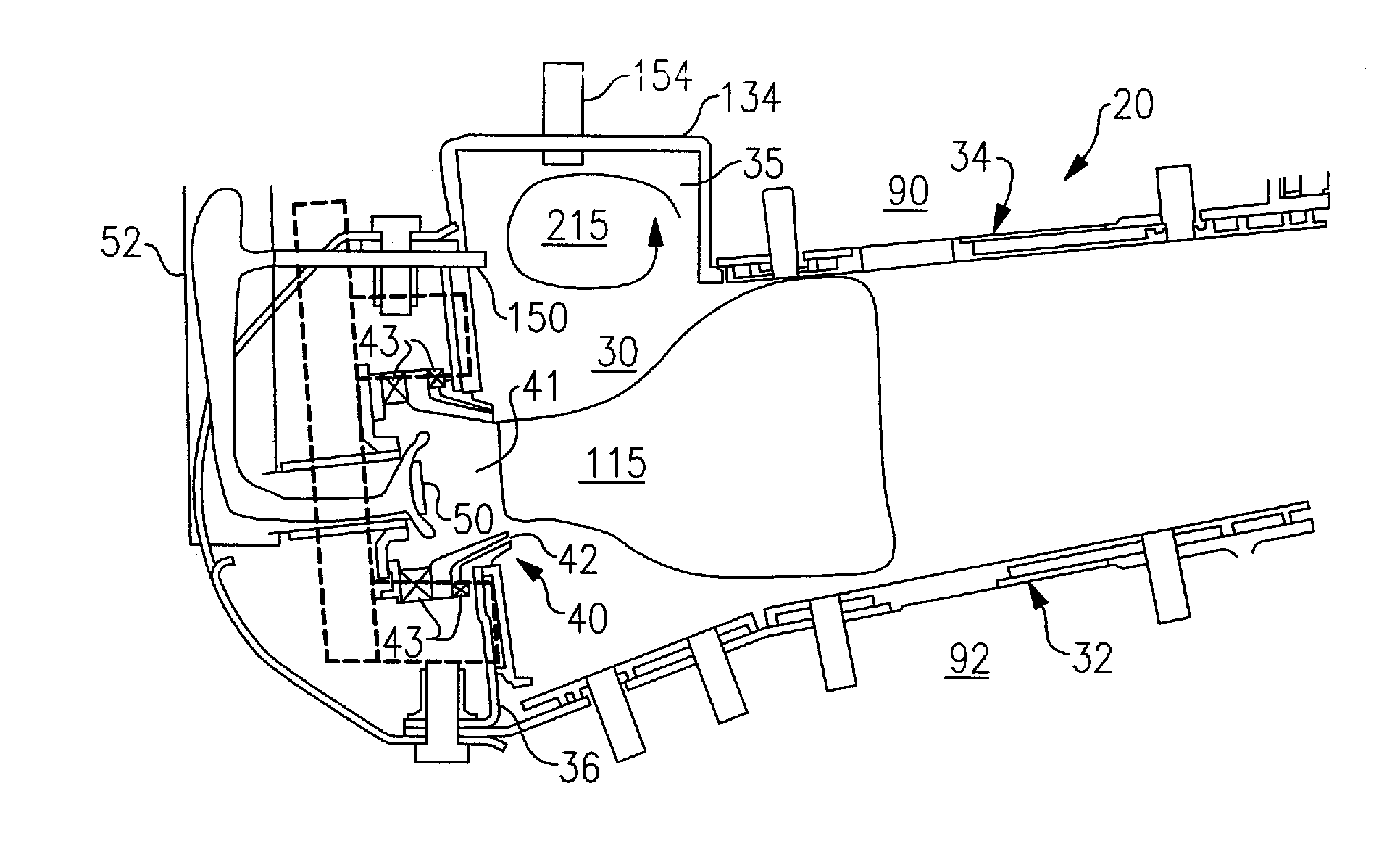
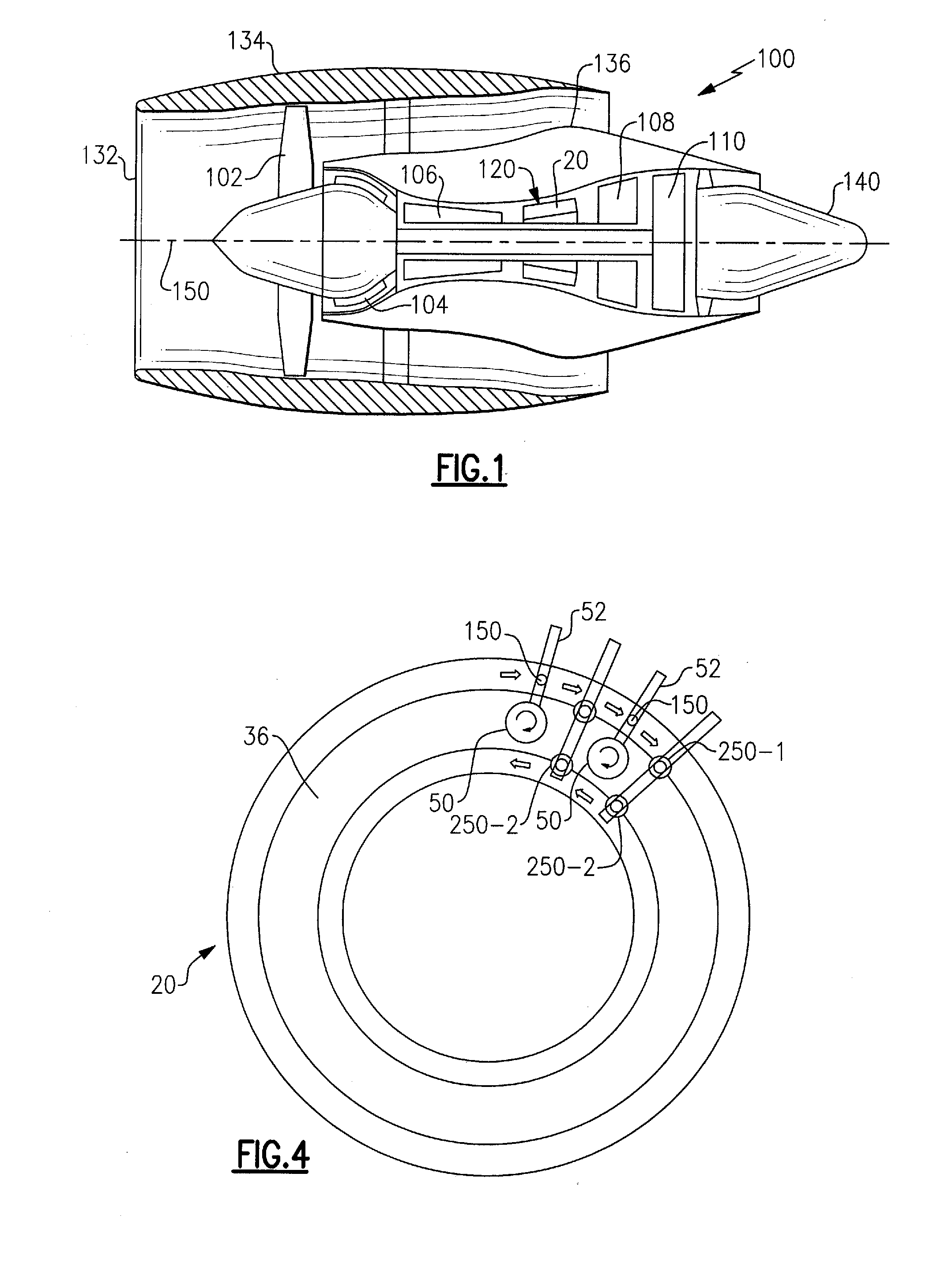
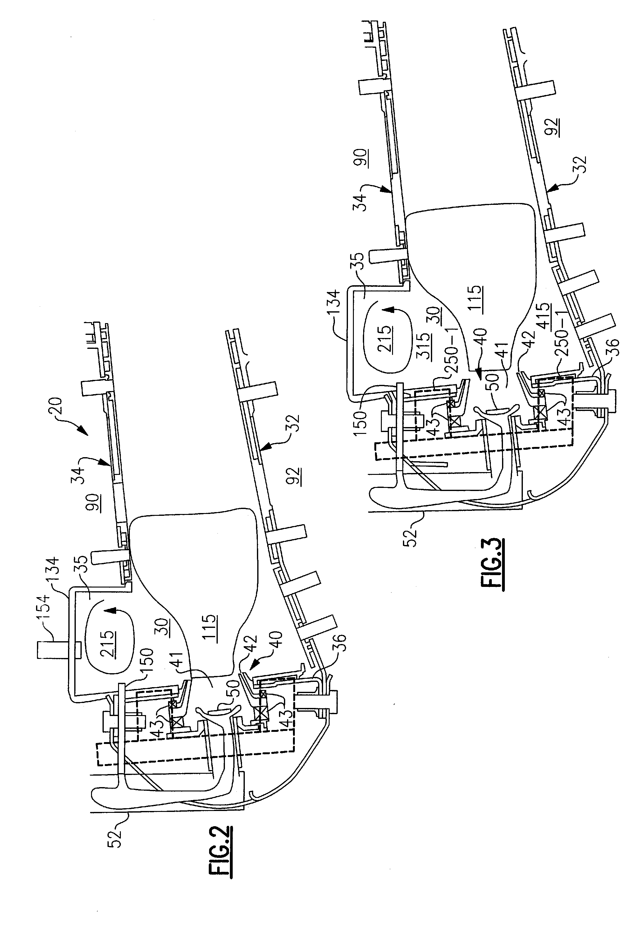
[0020]Referring now in FIG. 1, there is shown an exemplary embodiment of a turbofan gas turbine engine, designated generally as 100, that includes a turbine having rotating blades that could be repaired when the tips thereof are eroded by use of the method for repairing a turbine blade as disclosed herein. The turbofan gas turbine engine 100 includes, from fore-to-aft longitudinally about a central engine axis 150, a fan 102, a low pressure compressor 104, a high pressure compressor 106, a combustor module 120, a high pressure turbine 108, and a low pressure turbine 110. A nacelle forms a housing or wrap that surrounds the gas turbine engine 100 to provide an aerodynamic housing about gas turbine engine. In the turbofan gas turbine engine 100 depicted in the drawings, the nacelle includes, from fore to aft, the engine inlet 132, the fan cowl 134, the engine core cowl 136 and the primary exhaust nozzle 140. It is to be understood that the annular combustor 120 as disclosed herein is ...


PUM


Abstract

An annular combustor for a gas turbine engine is provided that facilitates staged combustion in a lean direct ignition (LDI) mode over an extended range of operating fuel air ratios. A method is also provided for operating a gas turbine engine over a power demand range that facilitates staged combustion in a lean direct ignition (LDI) mode over an extended range of operating fuel air ratios.

Description

FIELD OF THE INVENTION[0001]This invention relates generally to gas turbine engines and, more particularly, to an annular combustor for and a method for operating a gas turbine engine in a staged combustion mode.BACKGROUND OF THE INVENTION[0002]Gas turbine engines, such as those used to power modern commercial aircraft or in industrial applications, include a compressor for pressurizing a supply of air, a combustor for burning a hydrocarbon fuel in the presence of the pressurized air, and a turbine for extracting energy from the resultant combustion gases. Generally, the compressor, combustor and turbine are disposed about a central engine axis with the compressor disposed axially upstream of the combustor and the turbine disposed axially downstream of the combustor.[0003]An exemplary combustor features an annular combustion chamber defined between a radially inboard liner and a radially outboard liner extending aft from a forward bulkhead. The radially outboard liner extends circum...

Claims


Application Information

Patent Timeline
IPC IPC(8): F02C7/22F02C3/14
CPCF23R3/50F23R3/346
Inventor SNYDER, TIMOTHY S.
Owner RAYTHEON TECH CORP
Why Eureka
Try Eureka