Iteratively denoising color filter array images

a color filter array and image technology, applied in image enhancement, picture signal generators, instruments, etc., can solve the problems of reducing the ability to denoise chrominance information without, denoising full-color or cfa images, etc., to reduce computational effort and reduce luminance noise and chrominance noise of cfa images.

Inactive Publication Date: 2011-08-04
MONUMENT PEAK VENTURES LLC
View PDF18 Cites 14 Cited by
  • Summary
  • Abstract
  • Description
  • Claims
  • Application Information

AI Technical Summary

Benefits of technology

[0022]An advantage of the present invention is that both the luminance noise and the chrominance noise of the CFA image are reduced without the need of performing demosaicing (CFA interpolation) prior to or as part of the denoising process.
[0023]A further advantage of the present invention is a reduction of computational effort required to denoise the CFA image by only denoising a single chrominance channel at each pixel location rather than the usual multiple chrominance channels.
[0024]This and other aspects, objects, features, and advantages of the present invention will be more clearly understood and appreciated from a review of the following detailed description of the preferred embodiments and appended claims, and by reference to the accompanying drawings.

Problems solved by technology

Perona et al. only discuss denoising full-resolution grayscale (luminance) images and do not teach the denoising of full-color or CFA images.
Examples of this approach are given in U.S. Patent Application 2006 / 0152596 to Adams Jr. et al., entitled “Noise cleaning sparsely populated color digital images,” and U.S. Patent Application 2009 / 0052797 to Matsushita et al., entitled “Imaging device, image processing device, image processing method, program for image processing method, and recording medium having program for image processing method recorded thereon.” The problem with these approaches is that while chrominance values such as R-G are easy to compute, they are generally not devoid of luminance information, such as edge and text detail.
This, in turn, reduces the ability to denoise chrominance information without degrading luminance information in the image.

Method used


Image

  • Iteratively denoising color filter array images
  • Iteratively denoising color filter array images
  • Iteratively denoising color filter array images

Examples


Embodiment Construction

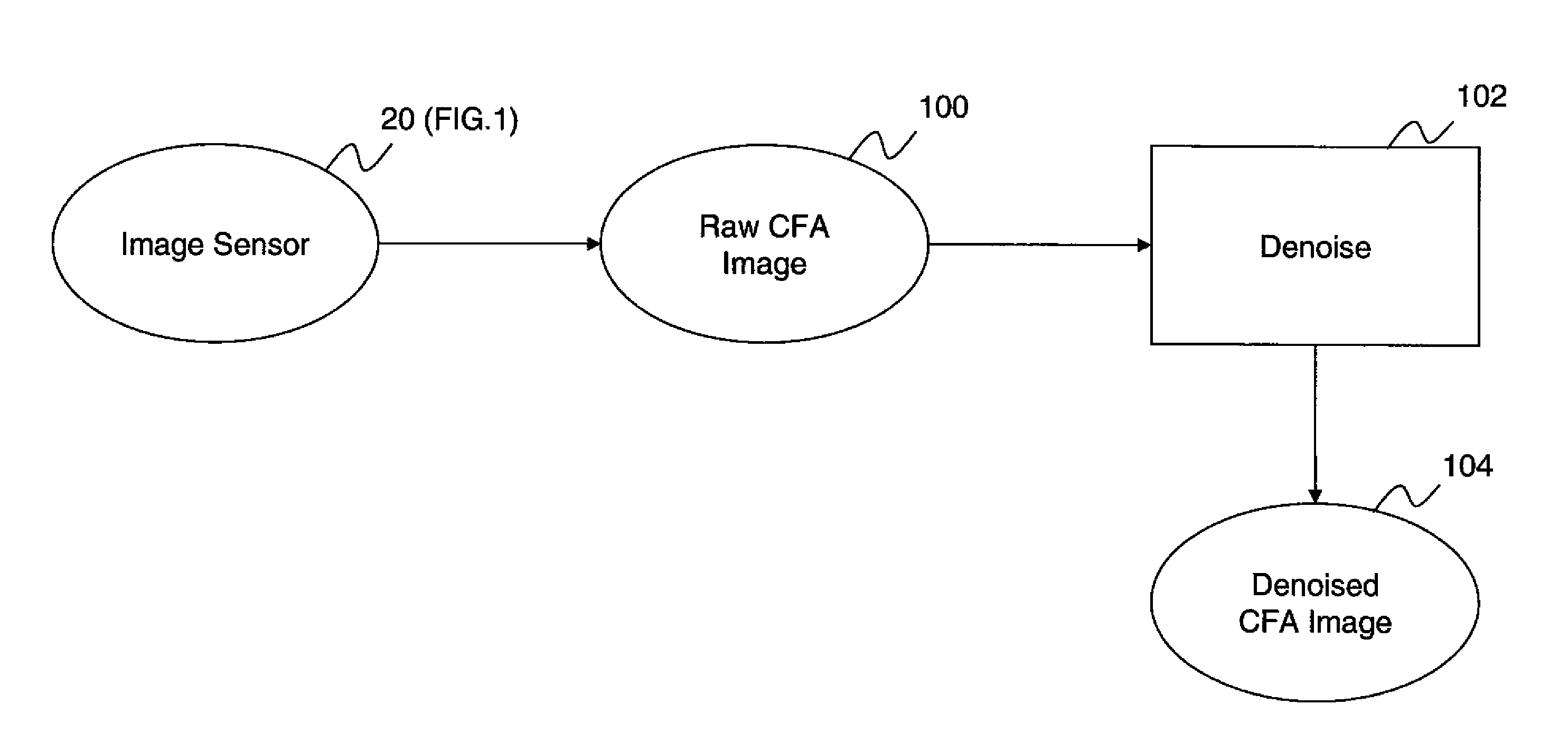
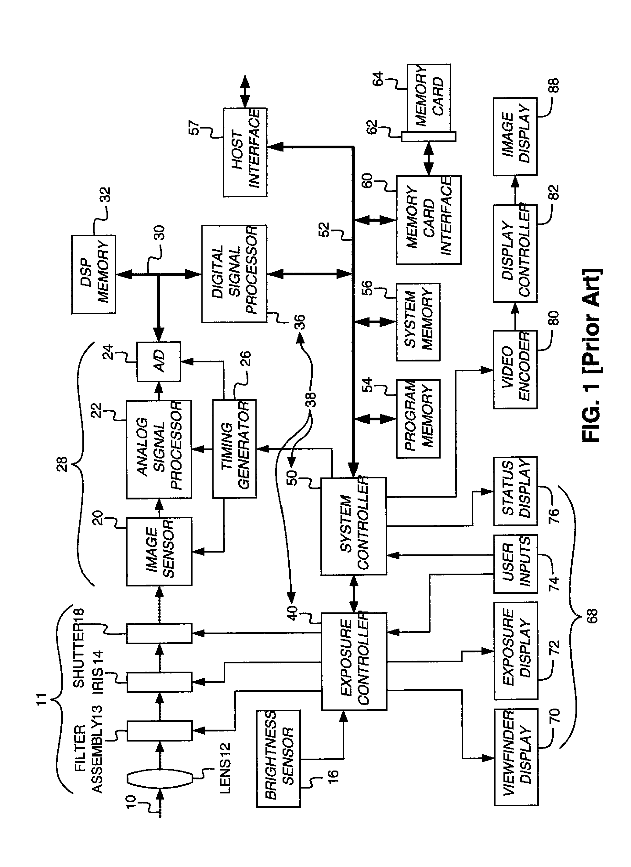
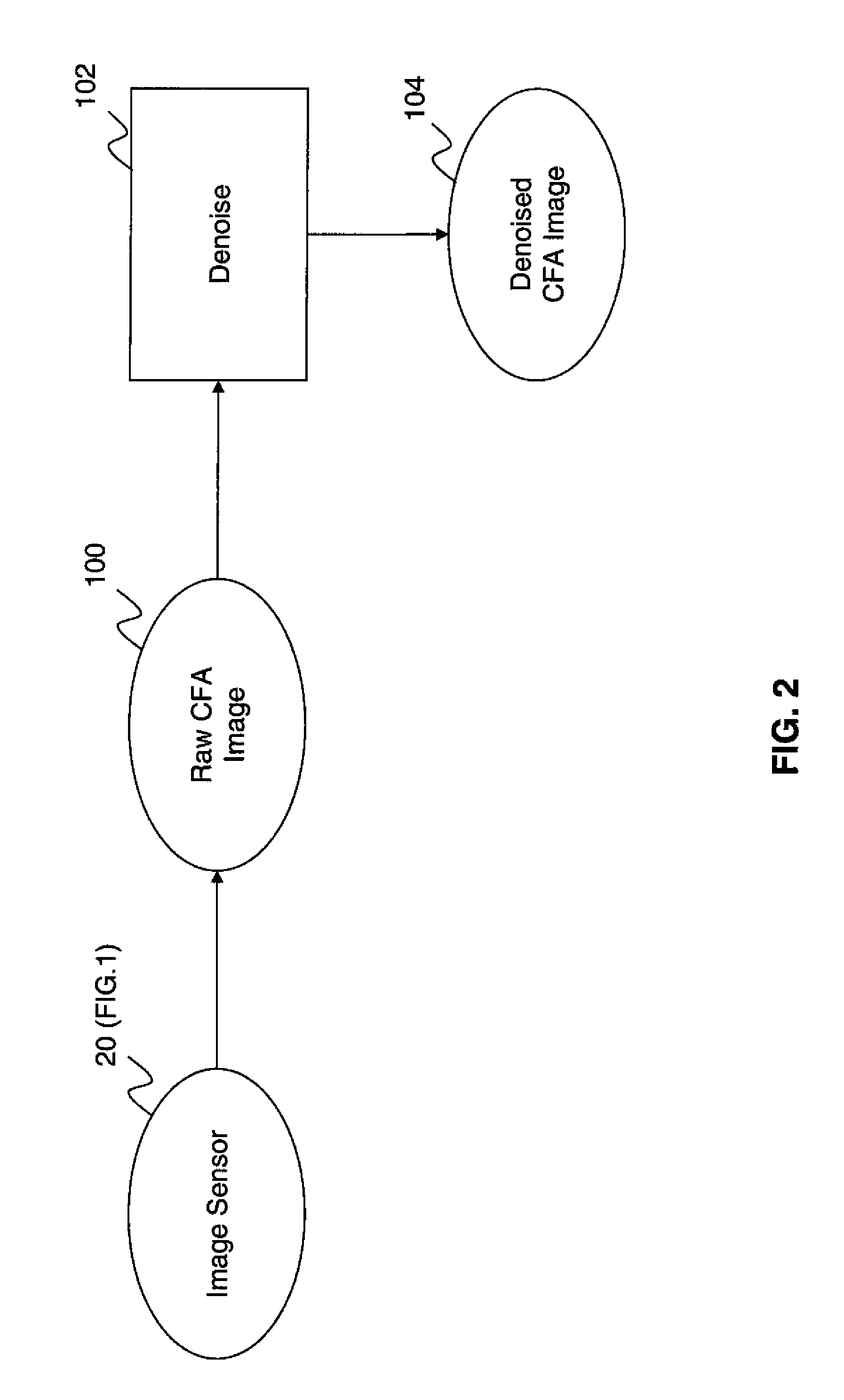
[0035]In the following description, a preferred embodiment of the present invention will be described in terms that would ordinarily be implemented as a software program. Those skilled in the art will readily recognize that the equivalent of such software can also be constructed in hardware. Because image manipulation algorithms and systems are well known, the present description will be directed in particular to algorithms and systems forming part of, or cooperating more directly with, the system and method in accordance with the present invention. Other aspects of such algorithms and systems, and hardware or software for producing and otherwise processing the image signals involved therewith, not specifically shown or described herein, can be selected from such systems, algorithms, components and elements known in the art. Given the system as described according to the invention in the following materials, software not specifically shown, suggested or described herein that is usef...


PUM


Abstract

A method for reducing noise in a color image captured using a digital image sensor having pixels being arranged in a rectangular minimal repeating unit. The method comprises, for a first color channel, determining noise reduced-pixel values using a first noise reducing process that includes computing weighted pixel differences by combining the pixel differences with corresponding local edge-responsive weighting values. The method further comprises a second noise reducing process that includes computing weighted chroma differences by combining chroma differences with corresponding local edge-responsive weighting values.

Description

CROSS-REFERENCE TO RELATED APPLICATIONS[0001]Reference is made to commonly assigned, co-pending U.S. patent application Ser. No. ______ (Docket 96120), entitled: “Denoising CFA Images Using Weighted Pixel Differences”, by J. Adams, et al., which is incorporated herein by reference.FIELD OF THE INVENTION[0002]The present invention relates to producing a noise-reduced color filter array image from a color filter array image using partial differential equation techniques.BACKGROUND OF THE INVENTION[0003]A single-sensor digital camera generally employs a color filter array (CFA) in order to capture full-color information from a single two dimensional array of light-sensitive pixels. The CFA comprises an array of color filters that filter the light being detected by each pixel. As a result, each pixel receives light from only one color, or in the case of a panchromatic or “clear” filter, from all colors. In order to reproduce a full-color image from the CFA image, three color values must...

Claims


Application Information

Patent Timeline
Patent Type & Authority Applications(United States)
IPC IPC(8): G06K9/00
CPCH04N9/045H04N23/84H04N25/134
Inventor ADAMS, JR., JAMES E.KUMAR, MRITYUNJAYMORALES, EFRAIN O.
Owner MONUMENT PEAK VENTURES LLC
Why Eureka
Try Eureka