
Microfluidic cell sorter and method

a microfluidic cell sorter and microfluidic technology, applied in biomass after-treatment, specific use bioreactors/fermenters, biochemistry apparatus and processes, etc., can solve the problems of less flexible and precise than desired, conventional cell sorting devices are complex, bulky, and expensiv

Inactive Publication Date: 2011-08-04
ORFLO TECH LLC
View PDF57 Cites 9 Cited by
  • Summary
  • Abstract
  • Description
  • Claims
  • Application Information

AI Technical Summary

Problems solved by technology

However, commercially available killing devices and methodologies, such as lethal reagents that may be added to a fluid sample, are less flexible and precise than desired.
Conventional cell sorting devices tend to be complex, bulky, and expensive.

Method used


Image

  • Microfluidic cell sorter and method
  • Microfluidic cell sorter and method
  • Microfluidic cell sorter and method

Examples


embodiment 80

[0040]With reference now to FIG. 4, an arrangement of structures illustrating certain principles of operation of the invention is indicated generally at 80. As illustrated, embodiment 80 includes an opaque member, generally indicated at 102, disposed between a radiation source 104 and a radiation detector 106. Opaque member 102 is provided as a portion of structure arranged to cause a desired fluid flow of a fluid sample including biological particles of interest. Sometimes, opaque member 102 may be made reference to as an interrogation layer, because layer 102 is associated with an interrogation zone. At least one orifice 108 is disposed in opaque member 102 to provide a flow path between a first side, generally indicated at 110, and a second side, generally indicated at 112. Orifice 108 may be characterized as having a through-axis 114 along which fluid may flow between the first and second sides 110 and 112 of opaque member 102, respectively.

[0041]The thickness, T1, of an opaque ...

embodiment 240

[0066]Although both of supply chamber 242 and waste chamber 244 are illustrated as being open, it is within contemplation for one or both to be arranged to substantially contain the fluid sample within a plumbing device that includes a multilayer embodiment 240. Also of note, although a top-down fluid flow is illustrated in FIG. 6, fluid flow may be established in either direction through orifice 108. In one reverse-flow configuration, the positions of supply chamber 242 and waste chamber 244 would simply be reversed from their illustrated positions. In an alternative reverse-flow arrangement, the positions of the radiation source 104 and detector 106 would be reversed from their illustrated positions.

[0067]The multilayer plumbing arrangement 240 illustrated in FIGS. 2 and 3 includes a top cap layer 254, a top channel layer 256, an opaque member 102, a bottom channel layer 258, and a bottom cap layer 260. Such layers can be stamped, e.g. die cut, or manufactured by using a laser or ...


PUM

PropertyMeasurementUnit
thicknessaaaaaaaaaa
thicknessaaaaaaaaaa
thicknessaaaaaaaaaa

Abstract

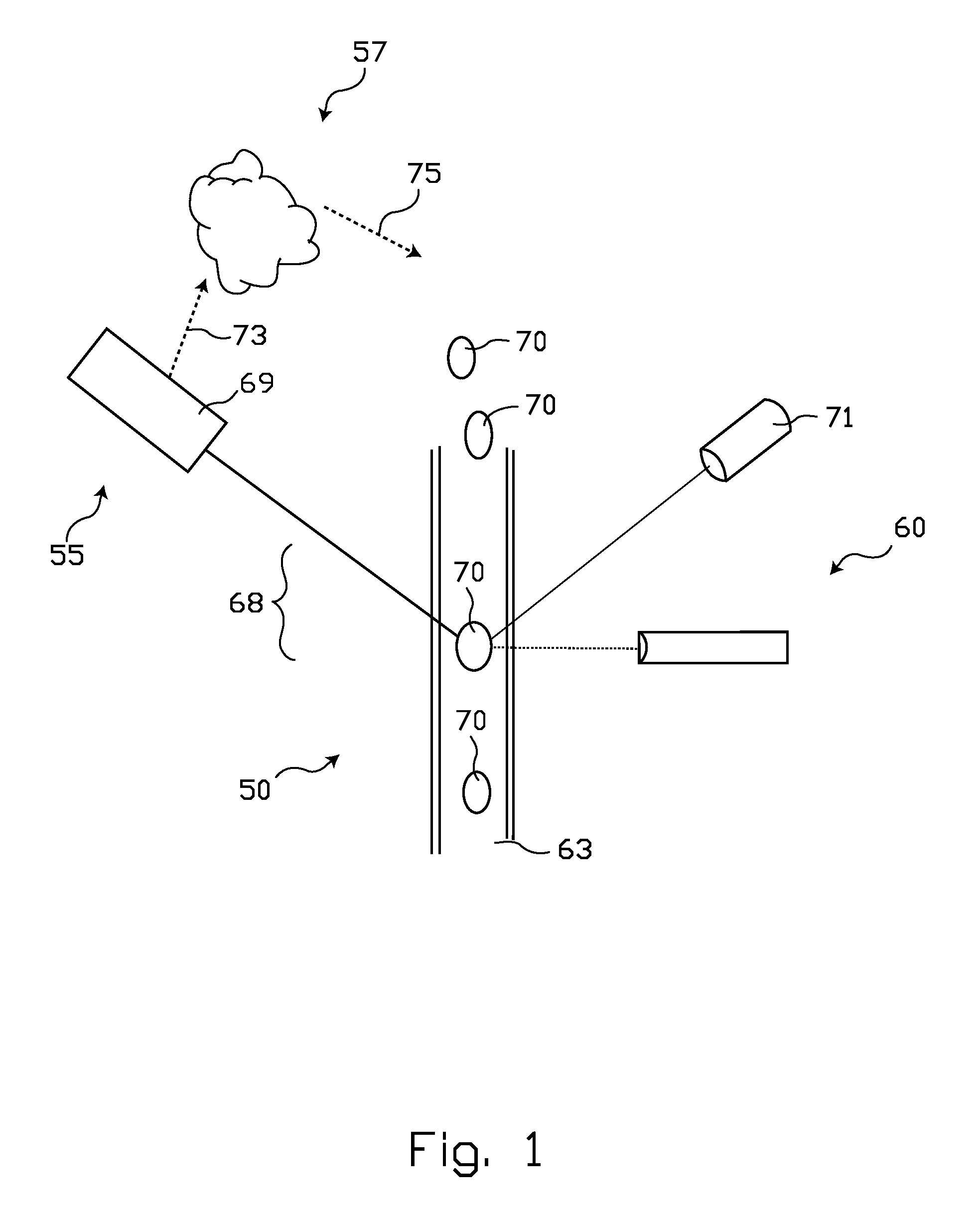
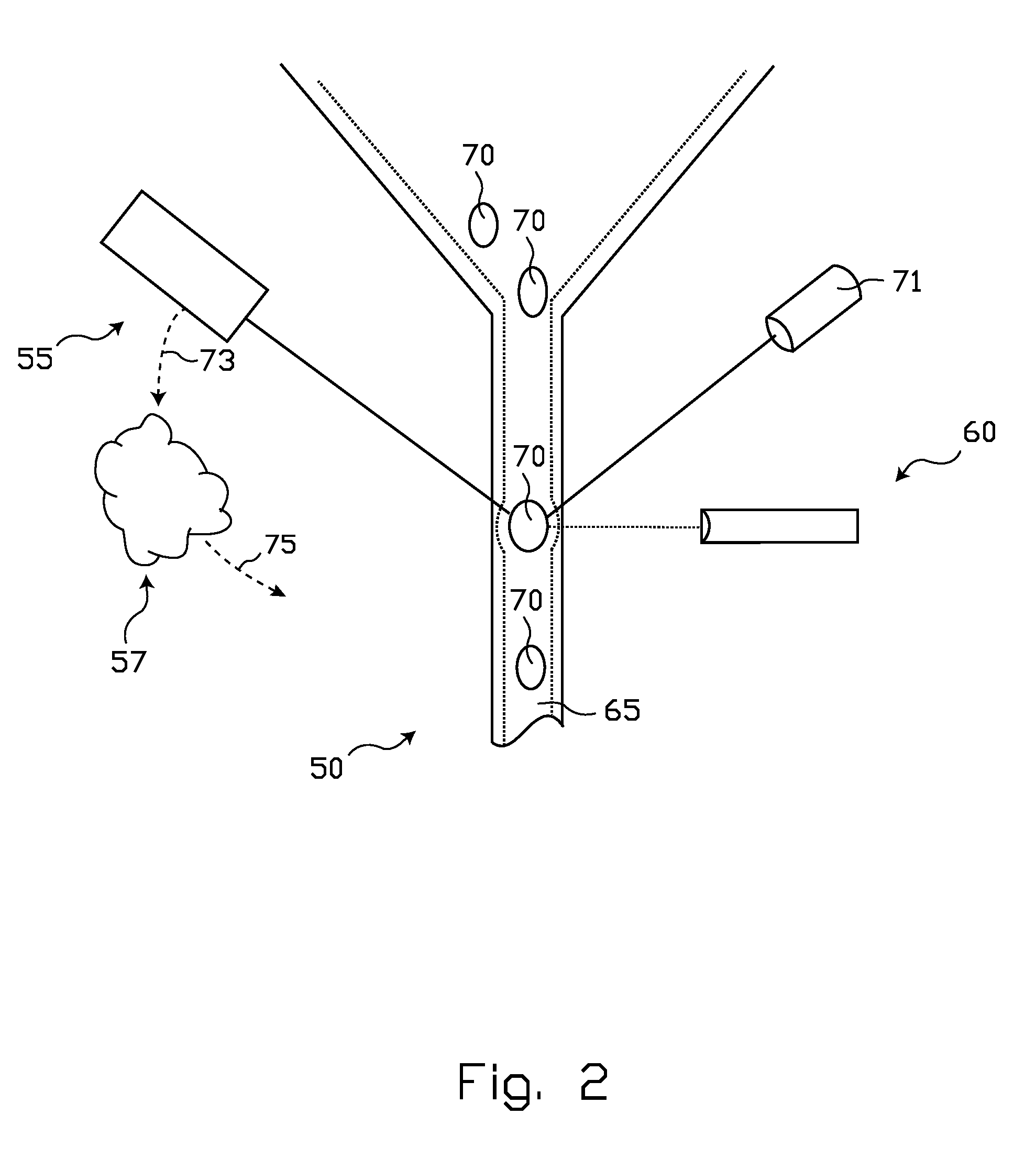
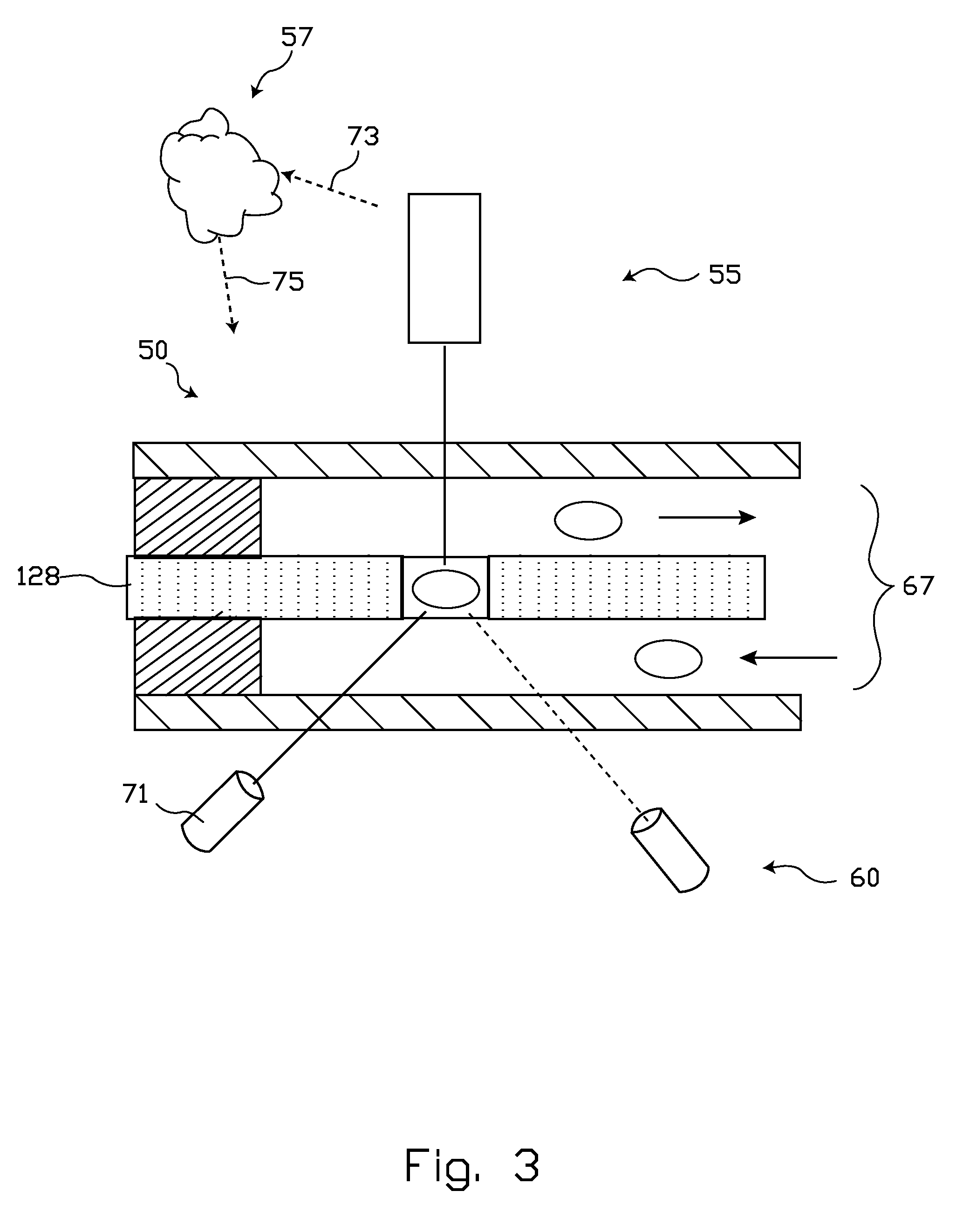
A biological particle sorting device and method of its use. The device includes structure arranged to urge biological particles into substantially single file travel through an interrogation zone. Operable alignment structure nonexclusively include sheathed fluid flow, capillary tubes, an orifice, and fluid microchannels. One or more detector, selected from a plurality of operable such structures, may be employed to sense the presence of a biologic particle in the interrogation zone. Certain exemplary detectors may operate on the Coulter principle, or may detect a Stokes' shift, or side-scatter radiation. Discrimination structure is generally provided to categorize particles as being in one or another sub-population of a mix of biological particles that may be carried in a fluid sample, such as by cell type, size, or the like. Killing structure, such as a laser, is disposed to neutralize all particles in any undesired sub-population while leaving undamaged the desired sub-population(s). The device may be operated to essentially purify (in a living or viable sense) a sample including biological particles that are carried in a fluid diluent.

Description

BACKGROUND[0001]1. Field of the Invention[0002]This invention relates to biological cell sorting and purification systems. Certain embodiments are particularly adapted for use in microfluidic plumbing arrangements to selectively kill one or more entire population of undesired cells.[0003]2. State of the Art[0004]It is sometimes desirable to sort one or more selected population of biological particles from a sample containing a plurality of different populations of particles. For example, it may be desired to select for culture only a subset of particles that are present in a mixture of particles. If physical cell sorting is not done, selective cell killing may sometimes be done instead. However, commercially available killing devices and methodologies, such as lethal reagents that may be added to a fluid sample, are less flexible and precise than desired.[0005]Conventional cell sorting devices tend to be complex, bulky, and expensive. An exemplary cell sorter based on a cytometric d...

Claims


Application Information

Patent Timeline
Patent Type & Authority Applications(United States)
IPC IPC(8): C12Q1/02C12M1/34
CPCC12M47/04
Inventor AYLIFFE, HAROLD E.KING, CURTIS S.
Owner ORFLO TECH LLC
Learn More