Light irradiating apparatus for cell sorter

a cell sorter and light irradiation technology, applied in the direction of optical radiation measurement, luminescent dosimeters, instruments, etc., can solve the problems of troublesome work, troublesome work, troublesome work, etc., to adjust the light axes of the laser light, and troublesome work

Inactive Publication Date: 2005-01-13
AISIN SEIKI KK
View PDF7 Cites 5 Cited by
  • Summary
  • Abstract
  • Description
  • Claims
  • Application Information

AI Technical Summary

Problems solved by technology

However, because an adjustment of the light axes of the laser light is highly difficult work, exchange of lasers 201, 202, 203 is really troublesome work.
However, the check and the replacement of each laser are also troublesome work because the lifetime period of each laser 201, 202, 203 is different.
Further, the lasers 201, 202, 203 are extremely costly, which increases a cost of the cell sorter.

Method used


Image

  • Light irradiating apparatus for cell sorter
  • Light irradiating apparatus for cell sorter
  • Light irradiating apparatus for cell sorter

Examples


first embodiment

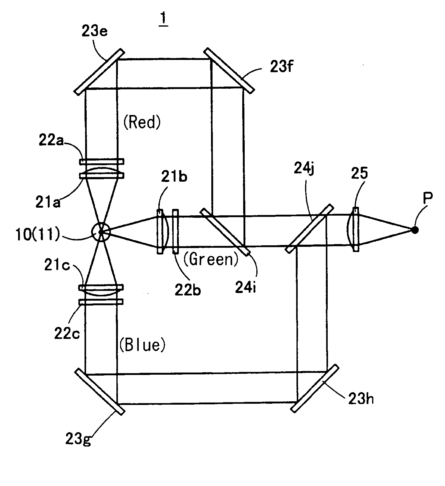
[0024]FIG. 1 shows a light irradiating apparatus 1 for a cell sorter according to the present invention. The irradiating light source for a cell sorter 1 includes a white light source 10. The irradiating light apparatus 1 is structured to irradiate plural monochromatic light separately extracted from the white light source 10 and is collected. As the white light source 10, for example, a high pressure mercury lamp is used.

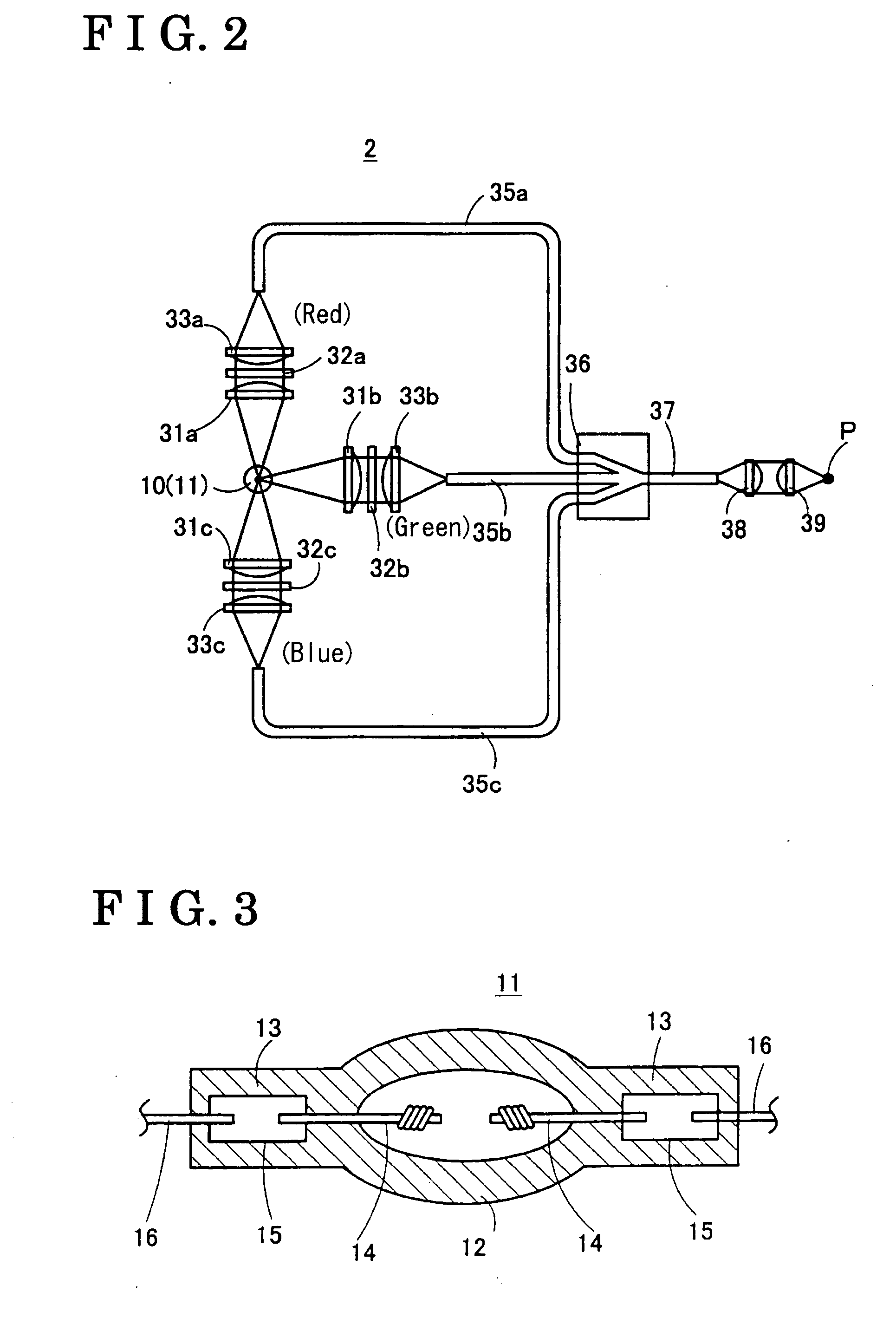
[0025] A structure of a high pressure mercury lamp is described, for example, in Japanese Patent Laid-Open Publication No. 1999-297269. FIG. 3 shows a drawing of a high pressure mercury discharge lamp according to the Publication No. 1999-297269. The high pressure mercury lamp 11 is made of a quartz glass, includes a discharge bulb portion 12 provided at the center, and a vertically elongated seal portions 13, 13 connected to both ends of the discharge bulb portion 12. First ends of a pair of electrodes 14, 14 are positioned having a clearance about 1.2 mm therebet...

second embodiment

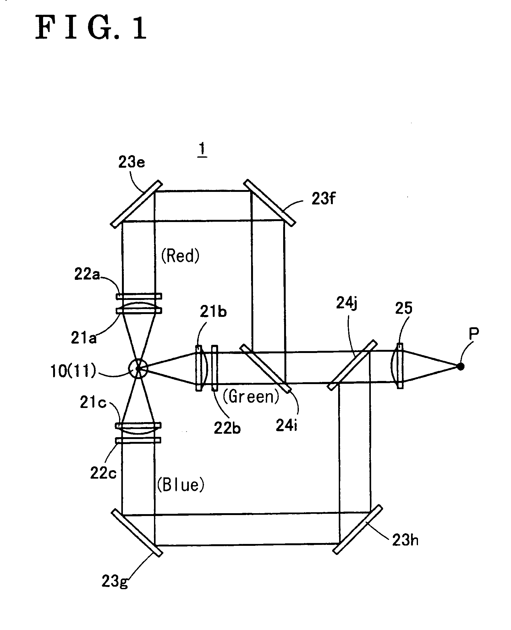
[0034] In the second embodiment, optical fibers 35a, 35b, 35c are used for directing member for monochromatic light. Plane-convex lenses 31a, 31b, 31c, optical filters 32a, 32b, 32c serving as a light extracting member, and focusing lenses 33a, 33b, 33c are respectively positioned at the three positions around the white light source 10 for collimating the light emitted from the white light source 10, and for selectively extracting the red, green and blue monochromatic light from the collimated light, and for focusing the light having passed through the optical filters 32a, 32b, 32c to the entrance of the optical fibers 35a, 35b, 35c. The optical fiber 35a, 35b, 35c are positioned at focused positions of the focused light. The optical fiber 35a, 35b, 35c are connected to the optical coupler 36. The light is coupled at the optical coupler 36 serving as a collecting member. The fiber 35a, 35b, 35c are connected at the optical coupler 36 to form a single optical fiber 37. A plane-convex...


PUM

PropertyMeasurementUnit
wavelengthaaaaaaaaaa

Abstract

A light irradiating apparatus for a cell sorter for irradiating light to a specimen in a sample liquid includes a light source for emitting light at a plurality of wavelengths, a light extracting member for separately extracting a plurality of monochromatic light from the emitted light, said respective monochromatic light having respective peak wavelengths, a directing member for directing said monochromatic light extracted by the light extracting member, and an irradiating member for simultaneously irradiating said plurality of monochromatic light to a position where the sample liquid passes through.

Description

CROSS REFERENCE TO RELATED APPLICATIONS [0001] This application is based on and claims priority under 35 U.S.C. § 119 to Japanese Patent Application 2003-194410 filed on Jul. 9, 2003, the entire content of which is incorporated herein by reference. FIELD OF THE INVENTION [0002] This invention generally relates to a light irradiating apparatus. More particularly, the present invention pertains to a light irradiating apparatus for a cell sorter. BACKGROUND [0003] Cell sorters detect, identify, collect and analyze large quantity of alive cell at high speed by irradiating light to the cell in a liquid fluid, and detecting side scattered light and fluorescence from the cell. With a known cell sorter described in Japanese Patent Laid-Open publication No.1994-288896 as shown in FIG. 5, a specimen is detected and selectively collected as follows. [0004] A sample liquid 100 including the specimen such as a dyed cell, or the like, is stored in a sample tube 101. A gas introduction tube 102 an...

Claims


Application Information

Patent Timeline
Patent Type & Authority Applications(United States)
IPC IPC(8): G01J3/02G01J3/10G01N15/14G01N21/01G01N21/64G02B26/00
CPCG01J3/02G01J3/0218G01J3/10G01N2021/6419G01N15/147G01N21/645G01N15/1434
Inventor KANAI, NARITOSHI
Owner AISIN SEIKI KK
Why Eureka
Try Eureka