Cell sorter

A sorter and cell technology, applied in the field of cell sorters, can solve the problems of inability to observe sorting, low processing capacity of sorting, and cell damage.

Inactive Publication Date: 2019-03-22
KK TOSHIBA
View PDF9 Cites 5 Cited by
  • Summary
  • Abstract
  • Description
  • Claims
  • Application Information

AI Technical Summary

Problems solved by technology

[0004] However, in this device, there are problems such as damage to cells during the separation process, low precision of separation, and low processing capacity of separation.
Furthermore, there is a problem that it is impossible to observe whether the fractionation of each cell is properly performed

Method used


Image

  • Cell sorter
  • Cell sorter
  • Cell sorter

Examples


no. 1 Embodiment approach

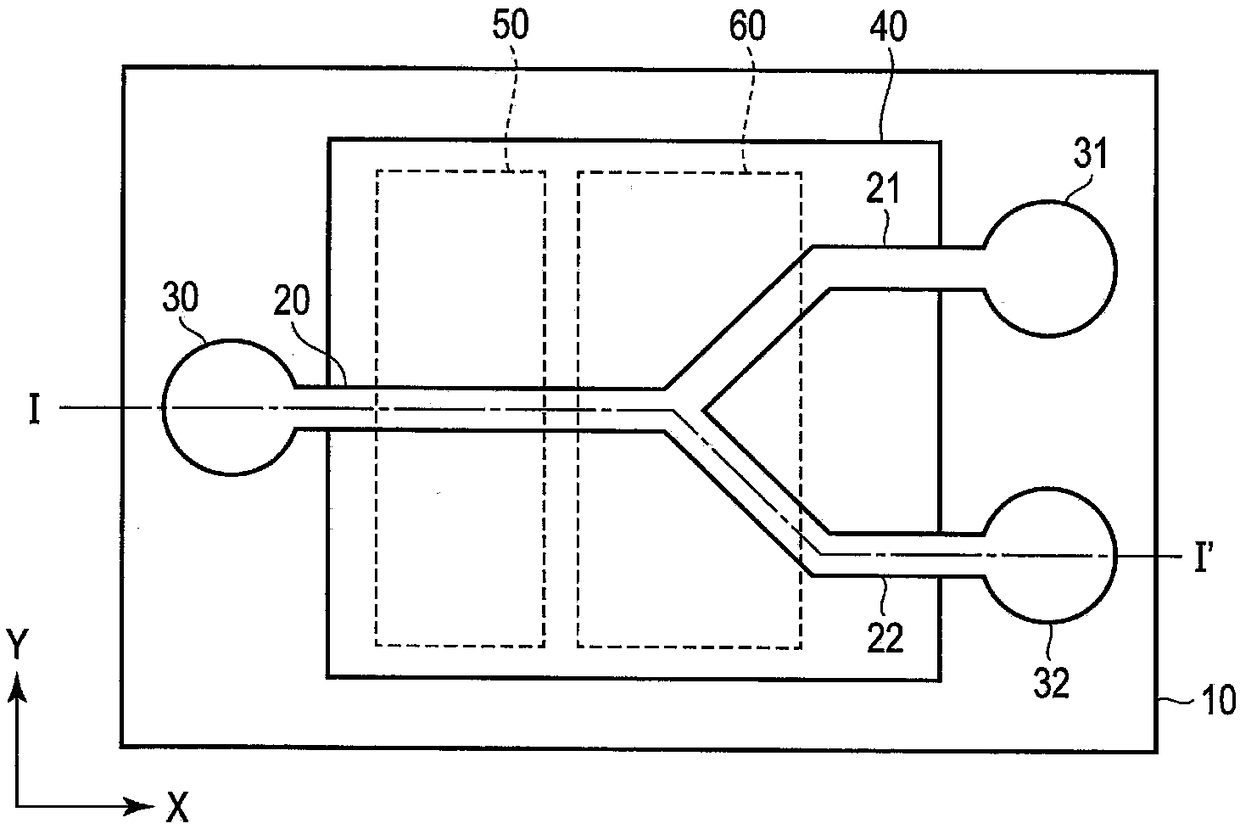
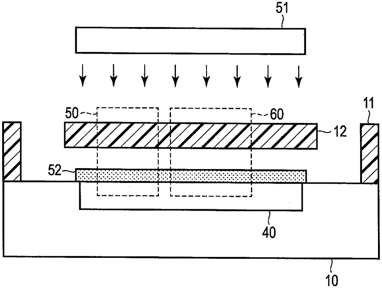
[0038] figure 1 and figure 2 is a diagram for explaining the schematic configuration of the cell sorter according to the first embodiment, figure 1 is a top view, figure 2 yes figure 1 The I-I' section view.

[0039] A flow path structure 11 made of resin such as PDMS (polydimethyl siloxane) is stacked on a substrate 10 such as a semiconductor substrate based on Si or glass epoxy. By selectively etching this channel structure 11, a channel (first channel) 20, branch channels (second channels) 21, 22, an input unit 30, and output units 31, 32 are provided. The upper surfaces of the respective flow paths 20 , 21 , and 22 are covered with a cover 12 made of the same material as the flow path structure 11 . In addition, the lid body 12 may be formed by embedding a sacrificial layer in the flow paths 20 , 21 , and 22 , depositing a thin film, and removing the sacrificial layer.

[0040] The flow channel structure 11 and the cover body 12 may be any material as long as it tr...

no. 2 Embodiment approach

[0062] Figure 6 It is a plan view showing a schematic configuration of the cell sorter according to the second embodiment. Additionally, for figure 1 The same parts are denoted by the same reference numerals, and detailed description thereof will be omitted.

[0063] This embodiment differs from the first embodiment described above in that a plurality of cell sorter elements having the same configuration as the first embodiment are arranged in a row.

[0064] A first cell sorter element 100 including a channel 20 , branch channels 21 and 22 , an input unit 30 , output units 31 and 32 , a determination unit 50 , and a separation unit 60 is provided on the substrate 10 . A second cell sorter element 200 having the same configuration as the first cell sorter element 100 is provided separately from the first cell sorter element 100 in the Y direction. The image sensor 40 is formed across a plurality of cell sorter elements 100, 200 so as to cover the flow path 20 of the first ...

no. 3 Embodiment approach

[0070] Figure 7 It is a plan view showing a schematic configuration of the cell sorter according to the third embodiment. Additionally, for figure 1 The same parts are denoted by the same reference numerals, and detailed description thereof will be omitted.

[0071] This embodiment differs from the previously described first embodiment in that a second-stage cell sorter element is provided at a subsequent stage of the first-stage cell sorter element having the same configuration as that of the first embodiment.

[0072] The channel (first channel) 20 of the primary cell sorter element, the first branch channel (second channel) 21, 22, the input unit 30, the first determination unit 50, and the first fractionator The part 60 is the same as that of the first embodiment. One end side of the second-stage re-branched flow path (third flow path) 21a, 21b is connected to the other end side of the first-stage branched flow path 21, and the other end side of the re-branched flow pa...


PUM


Abstract

An embodiment relates to a cell sorter that separates fine particles such as specific cells from a sample liquid. The cell sorter separates specific particles in the sample liquid without damage on particles such as cells in the sample liquid. The cell sorter according to the embodiment includes a flow channel (20) which supplies a sample liquid containing particles from one end side; a pluralityof branch channels (21, 22) which are connected to the other end side of the flow channel (20); an image sensor (40) which has a pixel region covering the flow channel (20) and the branch channels (21, 22); a determination unit (50) which determines the characteristics of the particles in the sample liquid from a measurement signal of the pixel region of the portion of the flow channel (20) of theimage sensor (40); and a separation unit (60) which is provided adjacently to the connection of the flow channel (20) and the branch channels (21, 22) and guides the particles in the sample liquid toany of the branch channels (21, 22) based on the determination result of the determination unit (50).

Description

[0001] This application is based on Japanese Patent Application No. 2017-178140 (filing date: September 15, 2017), and enjoys priority based on this application. This application incorporates the entire content of this application by reference. technical field [0002] This embodiment relates to a cell sorter for separating fine particles such as specific cells from a specimen fluid (sample fluid). Background technique [0003] In recent years, in the field of cell biology, a cell sorter for separating only specific cells from a cell mass in a sample fluid has been used. In this cell sorter, cells can be identified by irradiating a sample liquid (suspension or suspension of cells) jetted in droplet form with laser light and measuring scattered light or fluorescence. Furthermore, specific cells can be sorted into predetermined tubes by applying an electric field and / or a magnetic field. In addition, "fractionation" said here means "separation and taking out". [0004] Howe...

Claims


Application Information

Patent Timeline
Patent Type & Authority Applications(China)
IPC IPC(8): C12M1/00
CPCC12M47/04B03C1/288B03C5/026B03C2201/18G01N2015/149G01N2015/1006G01N15/147G01N15/1484B01L3/502761B01L2200/0652B01L2300/0645B01L2300/0816B01L2300/0864B01L2400/0421B01L2400/0424B01L2400/043B01L2400/0439B01L2400/0454B01L2400/0487B03C2201/24B03C2201/26B03C5/005B07C5/3427B07C5/3422G02B5/20
Inventor 今井快多香西昌平秋元阳介西垣亨彦小野冢丰永井弥夕
Owner KK TOSHIBA
Why Eureka
Try Eureka