Transportable liquid phase LNG sample apparatus and method

a liquid phase lng and sample apparatus technology, applied in the field of transportable liquid phase lng sample apparatus and method, can solve problems such as delay in field operations, and achieve the effect of convenient transportation

Active Publication Date: 2011-08-11
WELKER ENG
View PDF20 Cites 10 Cited by
  • Summary
  • Abstract
  • Description
  • Claims
  • Application Information

AI Technical Summary

Benefits of technology

[0013]The pre-cool cycle of the present invention is quick and gives technicians plenty of time to thereafter capture the sample of liquid phase LNG. The present sample apparatus weighs less than about 45 pounds filled with liquid phase Nitrogen and with liquid phase LNG so it is e

Problems solved by technology

Unfortunately, the cooling cycle, which must be completed prior to capturi

Method used


Image

  • Transportable liquid phase LNG sample apparatus and method
  • Transportable liquid phase LNG sample apparatus and method
  • Transportable liquid phase LNG sample apparatus and method

Examples


Embodiment Construction

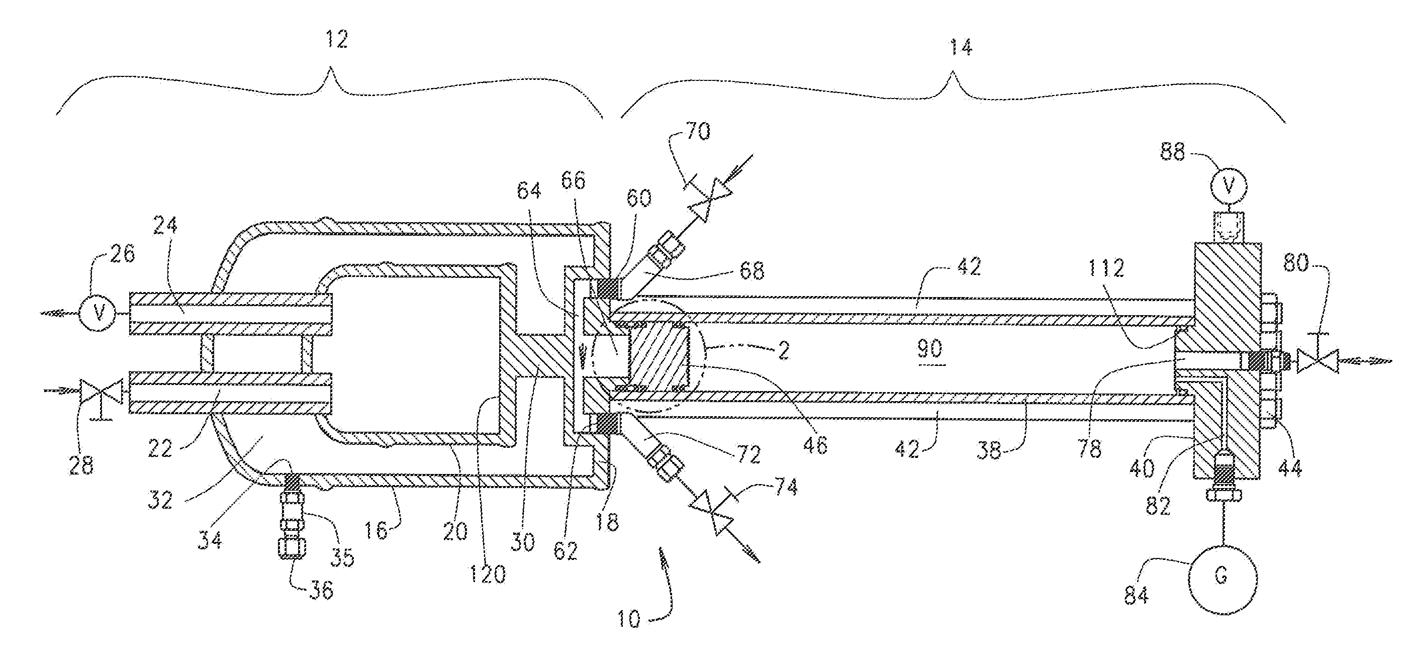
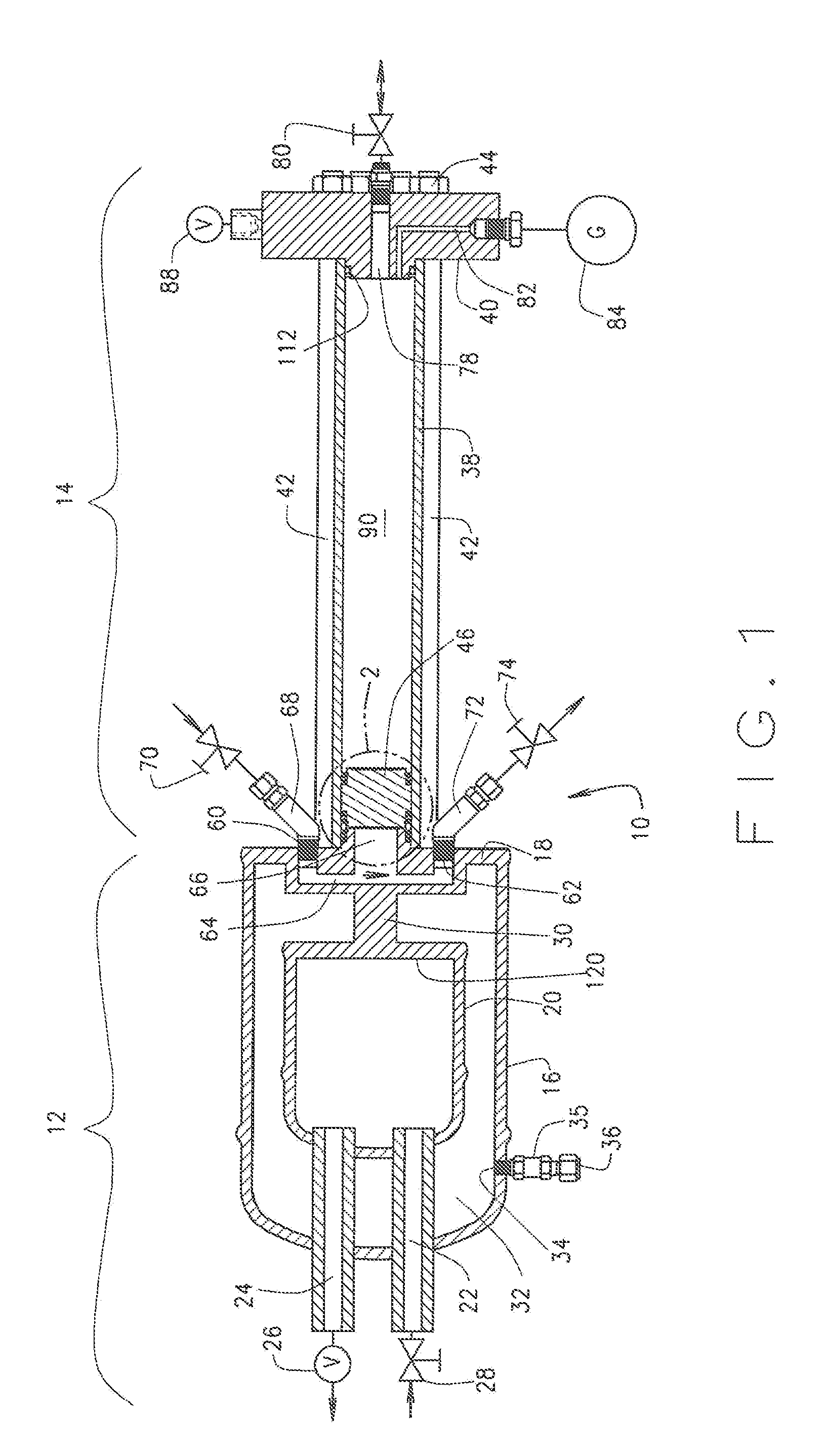
[0024]FIG. 1 is a section view of the Sample Apparatus 10, the vacuum flask identified by the bracket 12 and the sample container identified by the bracket 14. The vacuum flask is formed by an outer shell 16 connected to the sample end cap 18. An inner cryogenic vessel 20 includes a base 120; the inner cryogenic vessel 20 is surrounded by the outer shell of the vacuum flask. The inner cryogenic vessel 20 is filled with a cryogenic liquid to pre-cool the Sample Apparatus prior to capture of a liquid phase sample of LNG in the sample collection chamber 66, discussed in greater detail below.

[0025]A vacuum chamber 32 is defined by the outside surface of the cryogenic vessel, the sample end cap and the inside surface of the outer shell. A vacuum port 34 passes through the outer shell and is connected to a one way check valve 35 to maintain the vacuum in the vacuum chamber 32. A tube connection 36 is in fluid communication with the one-way check valve to facilitate connection to a vacuum ...


PUM


Abstract

A transportable Sample Apparatus includes a vacuum flask (Dewar flask) and integral sample container. The Sample Apparatus may be used to capture a liquid phase LNG sample at a custody transfer point and to transport the sample to a laboratory for analysis. Vaporization of the liquid phase sample may take place at a variety of different locations. For example, vaporization may begin and/or be completed during transport from the collection point to the laboratory. In another example, vaporization may begin and be completed in the laboratory. In yet another example vaporization may begin during transport and be completed at the laboratory. The gas phase sample is typically analyzed by a gas chromatograph for Btu content, among other things. Prior to capture of the sample, the Sample Apparatus goes through a pre-cool cycle to chill a sample end cap and other components to a temperature compatible with capture of a cryogenic liquid sample which is about −250° F.

Description

CROSS-REFERENCE TO RELATED APPLICATION[0001]This application is a continuation-in-part of prior U.S. application Ser. No. 12 / 234,602 entitled “LNG Sampling Cylinder and Method” filed on Sep. 19, 2008 which application is hereby incorporated by reference to the extent permitted by law.BACKGROUND OF THE INVENTION[0002]Some countries, like Japan, have little or no domestic supply of natural gas. To meet this demand, natural gas produced in Indonesia and / or the Middle East is liquefied and shipped to market in the liquid phase. Upon arrival in Japan, the LNG is offloaded from ships to land based LNG receiving terminals where it is stored in surface tanks in the liquid phase. When users need natural gas, the LNG is vaporized at the receiving terminal and pumped into pipelines for transmission to buyers and sellers. These pipelines vary in length. For example, some electrical generating plants in Japan are built proximate the LNG receiving terminals. Other areas of the world also import L...

Claims


Application Information

Patent Timeline
IPC IPC(8): G01N1/14
CPCG01N1/10G01N1/2042G01N2001/105G01N1/42
Inventor BOMBULIE, MICHAEL A.PEEBLES, TRACY D.
Owner WELKER ENG
Why Eureka
Try Eureka