Stove with assembly components

a technology of assembly components and stoves, which is applied in the field of stoves with assembly components, can solve the problems of increasing the cost of the final product, requiring additional assembly time and effort, and affecting the quality of the finished product, so as to facilitate assembly, reduce components, and reduce cost

Inactive Publication Date: 2011-08-11
ELECTROLUX DO BRASIL
View PDF11 Cites 8 Cited by
  • Summary
  • Abstract
  • Description
  • Claims
  • Application Information

AI Technical Summary

Benefits of technology

[0006]This disclosure is directed to household appliances including stoves with improved features and components for facilitating assembly. Using complimentary shaped and configured integral alignment protrusions and associated orifices formed in stove members including stove tops, sides, fronts and other features, assembly of the stoves may be expedited and made significantly more cost effective through reduced components and reduced time spent on assembly. The stove components are outfitted with complimentary structures to facilitate alignment and coupling together. These components may include coupling structures including integral alignment protrusions and orifices which may be stamped or otherwise formed in the structural and other components of the stove. The shapes, dimensions and arrangements simplify its fabrication and assembly and reduce or eliminate the need for conventional fasteners and tools for assembly processes such as assembly of the stove top with the sides, the table with the front finishing and the stove oven door.

Problems solved by technology

Use of these conventional fastening members in stove assembly adds cost to the final product, as a result of not only screws, clinches and pieces that must be acquired for this purpose, but also the time and manpower employed in these assembly tasks.
This additional labor, usually manual, requires further assembly time and effort and must be performed with reasonable accuracy.
This manner of assembly has disadvantages as the table is only overlapped to the finishing, and an alignment gap may occur.
Eventually table barbs may be exposed on the front part of the product potentially causing harm to users and others.
These rivets remain exposed and are subject to user interaction, are aesthetically unappealing and may pose as safety risk during operation.

Method used


Image

  • Stove with assembly components
  • Stove with assembly components
  • Stove with assembly components

Examples


Embodiment Construction

[0015]In the following description of the various embodiments, reference is made to the accompanying drawings, which form a part hereof, and in which is shown by way of illustration various embodiments in which the invention may be practiced. It is to be understood that other embodiments may be utilized and structural and functional modifications may be made without departing from the scope of the present invention.

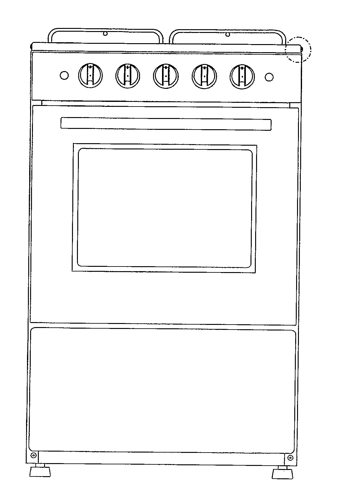
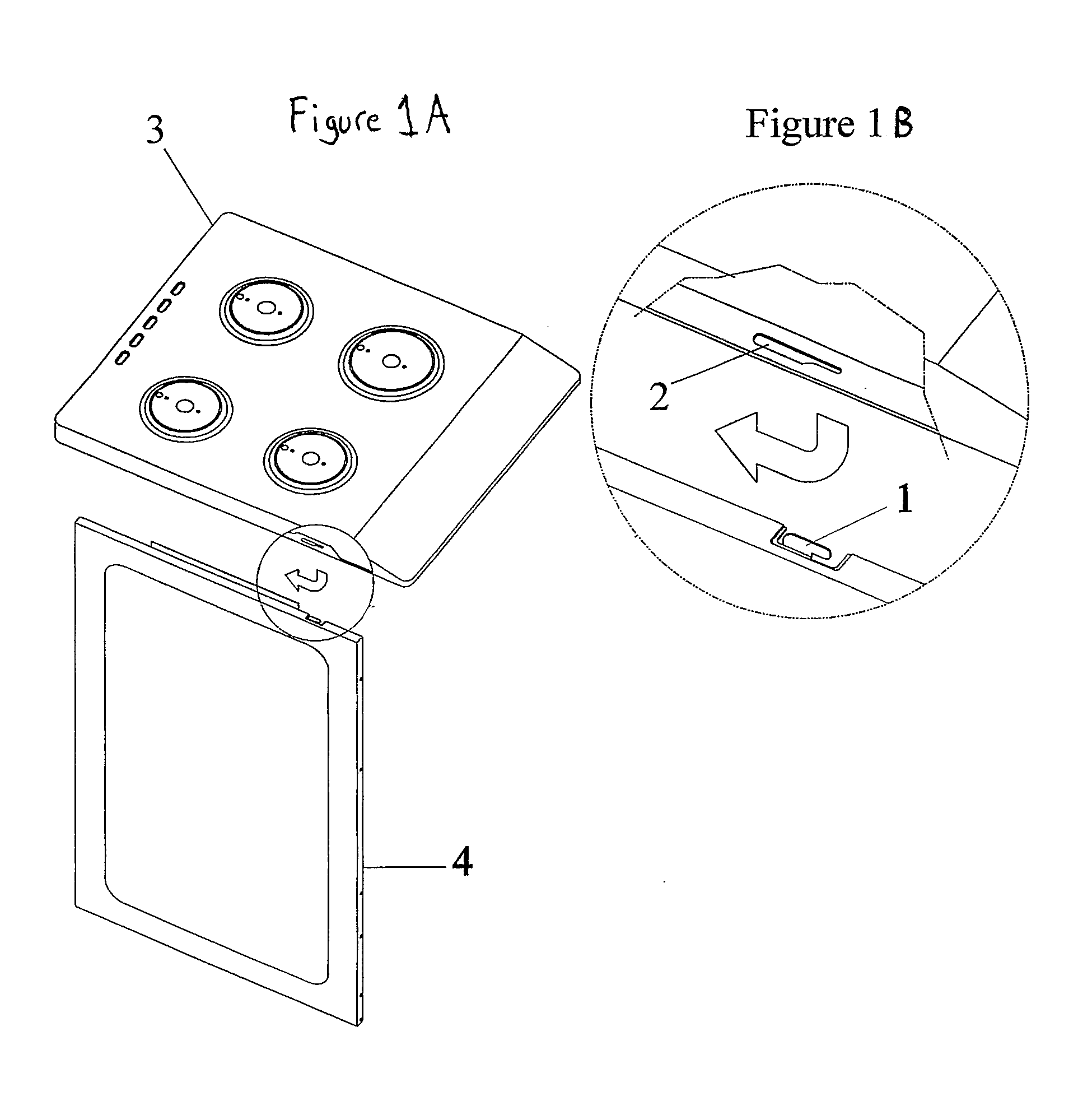
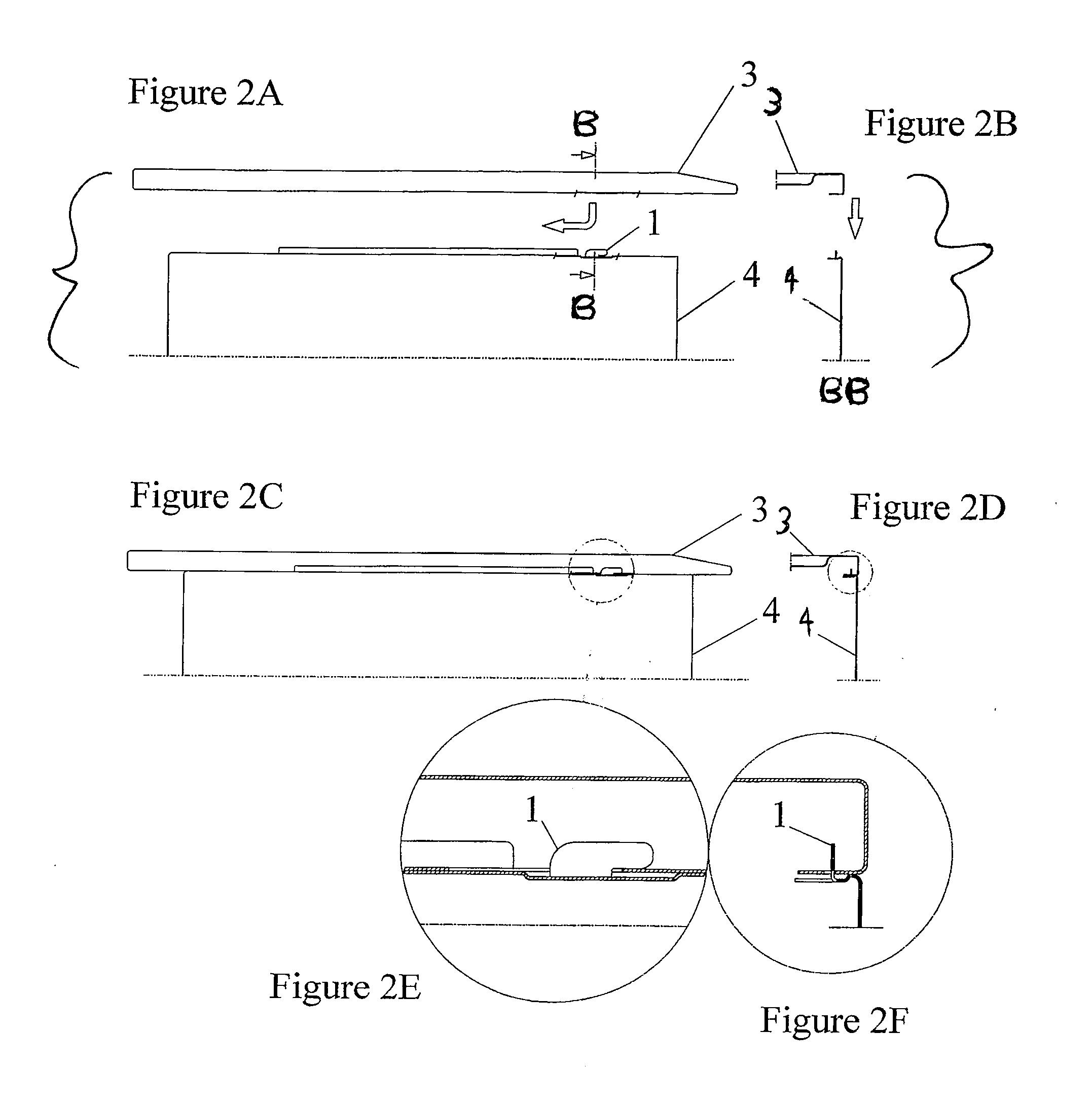
[0016]This disclosure illustratively describes various arrangements of stove components, comprised by couplings, which consist of associations of orifices (2) and integral alignment protrusion type cuttings (1), integrally formed on the component parts. Such devices are coupled together to assemble the table (3) with the stove side (4), as shown in FIGS. 1A to 4F, of the table (3) with the front finishing (5), in FIG. 5A-5F, and of both component parts (6a and 6b) of the stove oven door, in FIGS. 6A-6C. The term stove is well known to those skill in the art and may includ...


PUM


Abstract

A stove with a plurality of structural members coupled together and assembled to form a stove is disclosed. The stove may include a first structural member with an integral alignment protrusion formed in the structural member and extending from a main body of the structural member and a second structural member having an integral orifice complimentary in configuration and housed on the second structural member in a complimentary location to permit the integral alignment protrusion of the first structural member to be placed within the integral orifice and slid relative to the second structural member so as to couple the first and second structural members so as to form a portion of a stove. As such, stove tops, stove sides, kick plates, and other structural components in stoves may be easily assembled.

Description

[0001]This application claims priority to Brazilian Patent Application Number MU8802471-7 filed on Sep. 1, 2008 and is a continuation of PCT Application Number PCT / BR2009 / 000280 filed on Sep. 1, 2009, each herein incorporated by reference in their entirety.FIELD OF THE INVENTION[0002]This invention is directed to household appliances and construction and assembly of these products. Particularly, the present disclosure is directed to stoves with assembly components to facilitate assembly of the stove.BACKGROUND[0003]Currently stove parts are assembled and made using conventional fastening devices, such as screws or rivets, in addition to joint pieces, as illustrated in FIGS. 7A and 7B. Use of these conventional fastening members in stove assembly adds cost to the final product, as a result of not only screws, clinches and pieces that must be acquired for this purpose, but also the time and manpower employed in these assembly tasks. For example, assembly of the stove table with the si...

Claims


Application Information

Patent Timeline
Patent Type & Authority Applications(United States)
IPC IPC(8): F24C15/00F24C15/10
CPCF24C15/00F24C15/10F24C15/08F24C15/007
Inventor BEVILACQUA, ANTONIO CARLOS JUNIORGILBERTO, MARTINS ALVES
Owner ELECTROLUX DO BRASIL
Why Eureka
Try Eureka