Water Purification Apparatus and Method

Active Publication Date: 2011-08-11
VWS UK
View PDF13 Cites 34 Cited by
  • Summary
  • Abstract
  • Description
  • Claims
  • Application Information

AI Technical Summary

Benefits of technology

[0009]It is an object of the present invention to provide a water purification appar

Problems solved by technology

However, solenoids are limited in that the internal flow rate of the water dispense apparatus, and hence the flow rate of the dispense of the purified water stream, is conventionally set at a single and high value, and this does not allow for the easy dispense of slow or small volumes, particularly into smaller water collecting vessels such as beakers and flasks.
However, both such embodiments involve increasing costs for additional solenoids and additional hydraulic complexity.
However, such solenoids are still limited at very low and/or very accurate (such as drop wise) flows that can be desired or required when very p

Method used


Image

  • Water Purification Apparatus and Method
  • Water Purification Apparatus and Method
  • Water Purification Apparatus and Method

Examples


Embodiment Construction

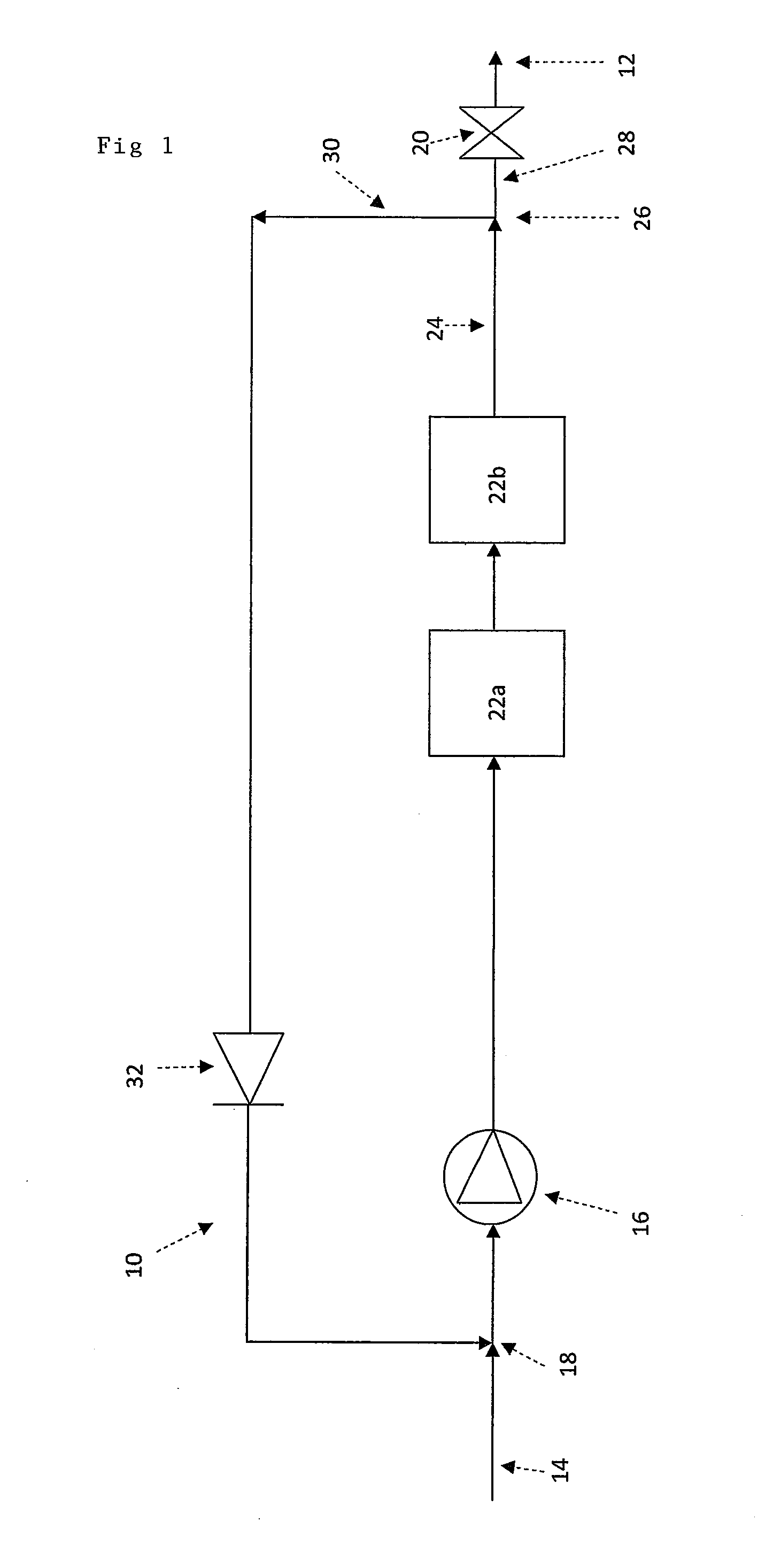
[0041]Referring to the drawings, FIG. 1 shows a water purification apparatus 10. The water purification apparatus 10 comprises one or more water purification components such as those described hereinabove. Such components may be integral and / or separable from a housing (not shown).

[0042]Separable components include ion-exchange cartridges and UV cartridges known in the art, but the present invention is not limited by the number, nature or location of the water purification components. The operations of water purification components are well known to those skilled in the art, and are generally intended to reduce and / or remove contaminants and impurities in water provided from a water input, so as to provide a purified water stream from at least one water dispense outlet.

[0043]Water purification components can include physical, magnetic, electrical and / or light-based components in any arrangement or line-up known in the art.

[0044]The water purification apparatus 10 is typically intend...


PUM


Abstract

A water purification apparatus comprising at least: (a) one or more water purification components to provide a purified water stream, preferably having a conductivity of less than 1 μS/cm; and (b) a stepper motor (35) to control the dispense of the purified water stream (28) from the water purification apparatus. Stepper motors can provide very fine and accurate control of the dispense of the purified water stream from the water purification apparatus, which control is unaffected by the flow or flow rate of the purified water stream.

Description

FIELD OF THE INVENTION[0001]The present invention relates a water purification apparatus and method, particularly, but not exclusively for laboratory water.BACKGROUND[0002]Water purification apparatus for use in laboratories and healthcare facilities are well known. Generally they involve the reduction and / or removal of contaminants and impurities to low levels. They typically contain a variety of technologies that remove particles, colloids, ionic species and organic substances and / or molecules.[0003]Water purification apparatus generally allow manual variation by a user of the volume of water to be dispensed, such as from drops to litres, and / or the speed (i.e. flow rate) of water dispense, again from drop-wise to a number of litres per minute.[0004]However, as well as manual dispensing based on a user physically operating a tap and manually gauging the volume of water being dispensed, frequently water purification apparatus provide for ‘automatic dispensing’, such as on a time ba...

Claims


Application Information

Patent Timeline
IPC IPC(8): F03B11/00
CPCB01L3/0293C02F1/008C02F1/32C02F1/42C02F9/00C02F9/005C02F2103/02F16K31/04C02F2301/02C02F2209/40Y10T137/8593C02F9/20
Inventor UNDERWOOD, LEEDOBSON, MATTHHEW
Owner VWS UK
Why Eureka
Try Eureka