Zero-Wall Clearance Linkage Mechanism for a Lifting Recliner

a technology of linkage mechanism and lifting chair, which is applied in the direction of chairs, mechanical control devices, instruments, etc., can solve the problems of collapsed mechanical arrangement, unextended ottoman, and unit requirements for relatively complex linkage mechanisms, and achieve the effect of convenient and cost-effectiv

Active Publication Date: 2011-08-11
L & P PROPERTY MANAGEMENT CO
View PDF12 Cites 47 Cited by
  • Summary
  • Abstract
  • Description
  • Claims
  • Application Information

AI Technical Summary

Benefits of technology

[0006]Embodiments of the present invention seek to provide a simplified lifter-recliner linkage mechanism that can be assembled to a single compact motor and that can be adapted to essentially any style of seating unit. In an exemplary embodiment, the compact motor in concert with the linkage mechanism can achieve full movement and sequenced adjustment of the seating unit when being automatically adjusted between the closed, extended, reclined, and seat-lift positions. The compact motor may be employed

Problems solved by technology

Additionally, if the seating unit includes an ottoman attached with a mechanical arrangement, the mechanical arrangement is collapsed such that the ottoman is not extended.
However, these seating units require relatively complex linkage mechanisms to afford this capability.
The complex linkage assemblies limit certain design aspects when incorporating automation.
In particular, the geometry of these linkage assemblies impose constraints on incorporating or mounting a single motor thereto.
Such constraints include the motor, during extensi

Method used


Image

  • Zero-Wall Clearance Linkage Mechanism for a Lifting Recliner
  • Zero-Wall Clearance Linkage Mechanism for a Lifting Recliner
  • Zero-Wall Clearance Linkage Mechanism for a Lifting Recliner

Examples


Embodiment Construction

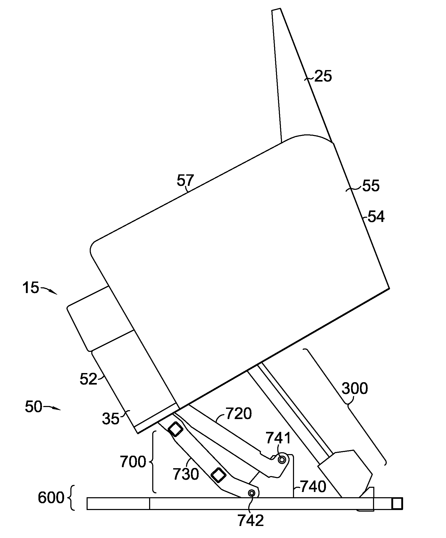
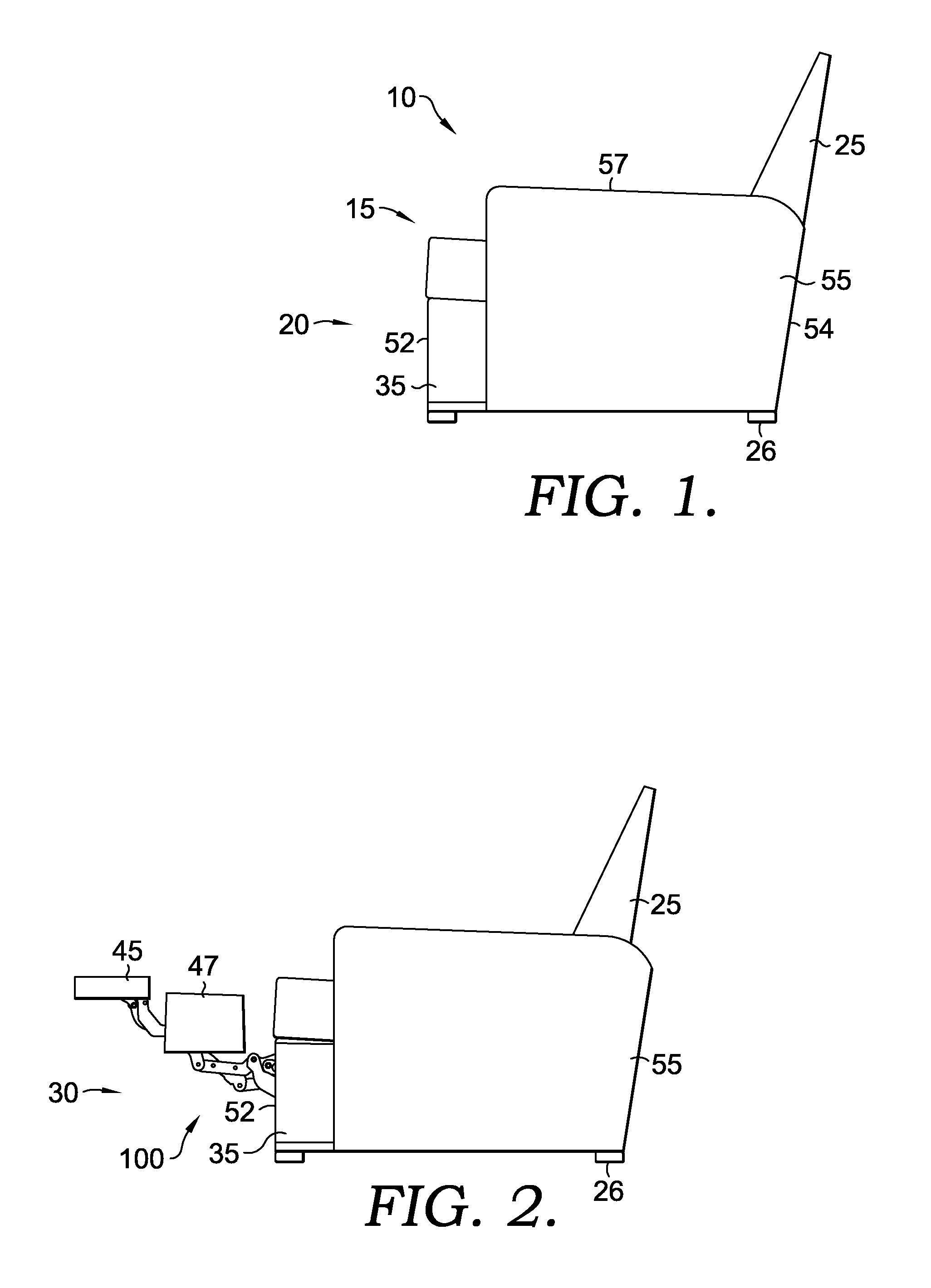
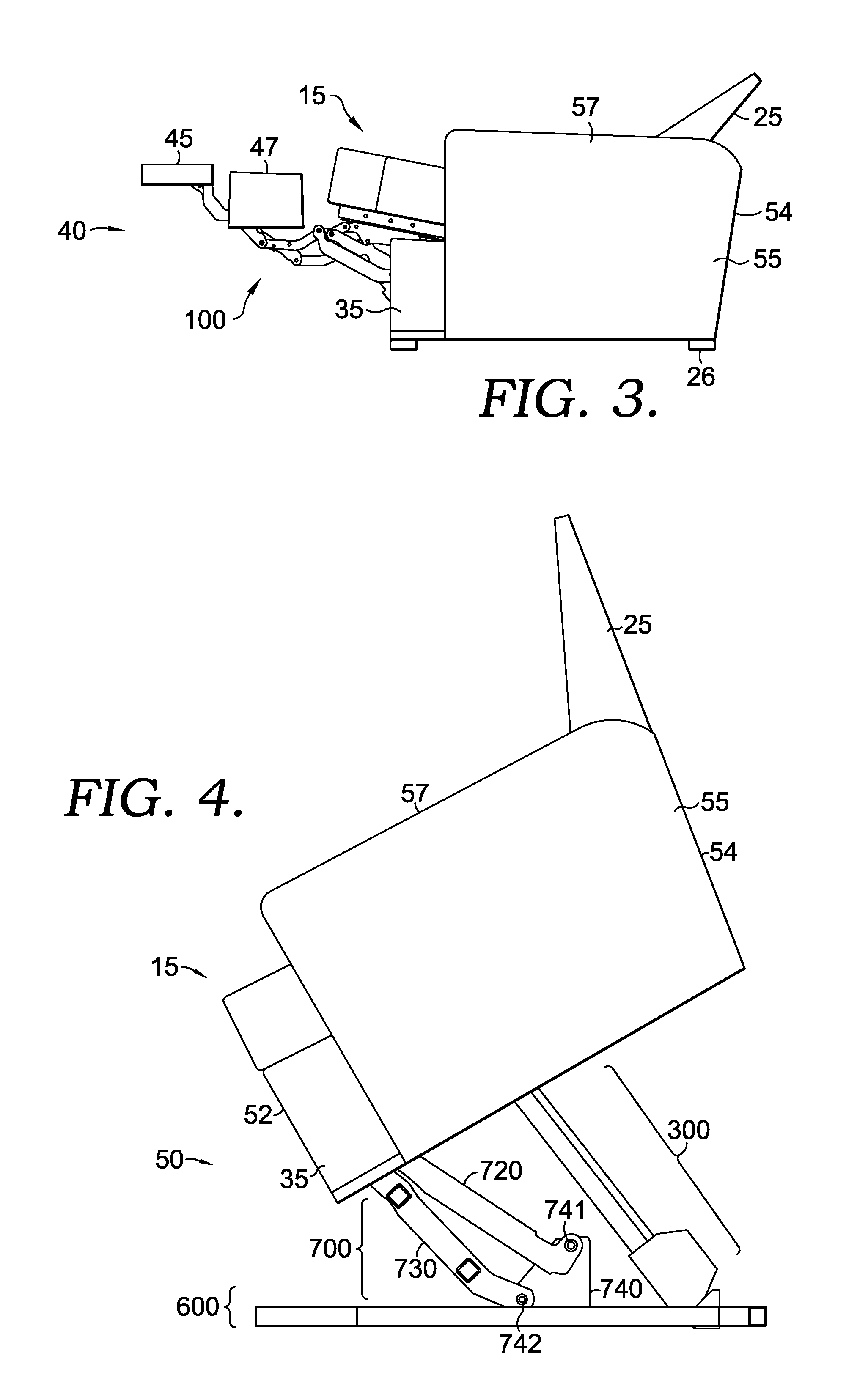
[0029]FIGS. 1-4 illustrate a seating unit 10. Seating unit 10 has a seat 15, a backrest 25, legs 26 (e.g., support bushings or a support assembly 600 that rests upon an underlying surface), at least one linkage mechanism 100, at least one lift assembly 700, a motor assembly 300, a first foot-support ottoman 45, a second foot-support ottoman 47, a stationary base 35, and a pair of opposed arms 55. Stationary base 35 has a forward section 52, a rearward section 54, and is supported by the legs 26 or the support assembly 600 (see FIG. 4), which vertically suspends the stationary base 35 above the underlying surface (not shown). In addition, the stationary base 35 is interconnected to the seat 15 via the linkage mechanism(s) 100 that are generally disposed between the pair of opposed arms 55, and the rearward section 54. Seat 15 is moveable over the stationary base 35 during adjustment of the seating unit 10, or when raising or lowering the seating unit 10 into or out of a seat-lift pos...


PUM


Abstract

A seating unit that includes a linkage mechanism adapted to move the seating unit between seat-lift, closed, extended, reclined, and seat-lift positions is provided. The linkage mechanism includes a seat-mounting plate mounted to a footrest assembly, a base plate fixedly mounted to a lift assembly, a back-mounting link rotatably coupled to the seat-mounting plate, a seat-adjustment assembly with a bellcrank, and a linear actuator for automating adjustment of the linkage mechanism. In operation, a stroke in a first phase of the linear actuator generates a force on the bellcrank that translates the seat-mounting plate rearward in a consistent angle of inclination and rotates the back-mounting link from a reclined to an upright orientation. A stroke in a second phase acts to collapse the footrest assembly. A stroke in a third phase causes the lift assembly to raise and tilt the seating unit, thereby accommodating egress and ingress of an occupant.

Description

CROSS-REFERENCE TO RELATED APPLICATIONS[0001]This application claims the benefit of U.S. Provisional Application No. 61 / 303,666, filed Feb. 11, 2010, entitled “ZERO-WALL CLEARANCE LINKAGE MECHANISM FOR A LIFTING RECLINER,” herein incorporated by reference.BACKGROUND OF THE INVENTION[0002]The present invention relates broadly to motion upholstery furniture designed to support a user's body in an essentially seated disposition. Motion upholstery furniture includes recliners, incliners, sofas, love seats, sectionals, theater seating, traditional chairs, and chairs with a moveable seat portion, such furniture pieces being referred to herein generally as “seating units.” More particularly, the present invention relates to an improved linkage mechanism developed to accommodate a wide variety of styling for a seating unit, which is otherwise limited by the configurations of linkage mechanisms in the field. Additionally, the improved linkage mechanism of the present invention provides for r...

Claims


Application Information

Patent Timeline
IPC IPC(8): A47C1/035A61G5/14A47C1/038A47C1/0355
CPCA47C1/035Y10T74/20A47C1/029A61G5/14Y10S297/10
Inventor LAWSON, GREGORY M.BRYANT, JASON ALLAN
Owner L & P PROPERTY MANAGEMENT CO
Why Eureka
Try Eureka