Eyewear for acquiring video imagery

Inactive Publication Date: 2011-08-11
HUNTER SPECIALTIES +1
24 Cites 42 Cited by

AI-Extracted Technical Summary

Problems solved by technology

In hunting, it is at times desirable to record a hunting event.
Yet, there are difficulties in recording the hunt.
Although a hunter could rely on others to record their hunt, there may not be others available...

Benefits of technology

[0006]It is a further object, feature, or advantage of the present invention to provide a device which has an eyewear frame with an integral camera which is mounted in such a manner that it does not impede performance of the user in hunting or other sports.
[0007]It is a still further object, feature, or advantage of the present invention to provide a device which may be used to record an event from the point-of-view of a participant in the event.
[0008]It is another object, feature, or advantage of the present invention to provide a device which is easy to use.
[0009]Yet another object, feature, or advantage of the present invention is ...

Abstract

An article of eyewear includes an eyeglass frame having an integrally formed camera enclosure, and an imaging sensor disposed within the camera enclosure. The eyeglass frame may have a camouflage pattern. A system for recording video includes an eyeglass frame having an integrally formed camera enclosure, an imaging sensor disposed within the camera enclosure, and a wireless transceiver disposed within the eyeglass frame. A method of documenting a hunt using an article of eyewear is provided. The method includes providing the article of eyewear, the article of eyewear comprising (a) an eyeglass frame having an integrally formed camera enclosure, (b) an imaging sensor disposed within the camera enclosure, and (c) wherein the eyeglass frame having a camouflage pattern. The method further includes activating a video recording functionality of the article of eyewear during the hunt and video recording the hunt using the article of eyewear.

Application Domain

Television system detailsColor television details +2

Technology Topic

TransceiverVideo recording +4

Image

  • Eyewear for acquiring video imagery
  • Eyewear for acquiring video imagery
  • Eyewear for acquiring video imagery

Examples

  • Experimental program(1)

Example

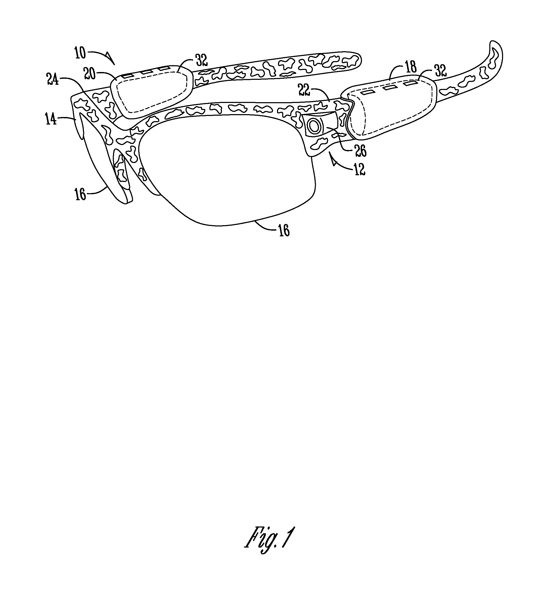
[0023]FIG. 1 illustrates a device 10. The device 10 includes an eyewear frame 14. Here, the eyewear frame 14 is patterned with camouflage as may be appropriate for certain uses of the device 10, such as by an individual who is recording a hunt. Although potentially advantageous, the eyewear frame 14 need not be patterned with camouflage and may be a solid color or otherwise patterned. The frame 14 supports a pair of lenses 16. The lenses 16 may be prescription lenses, polycarbonate shooting lenses, polarized lenses, non-polarized lenses, or other type of lenses. A pair of temples 18, 20 are pivotally connected to the frame 14 at hinges 22, 24.
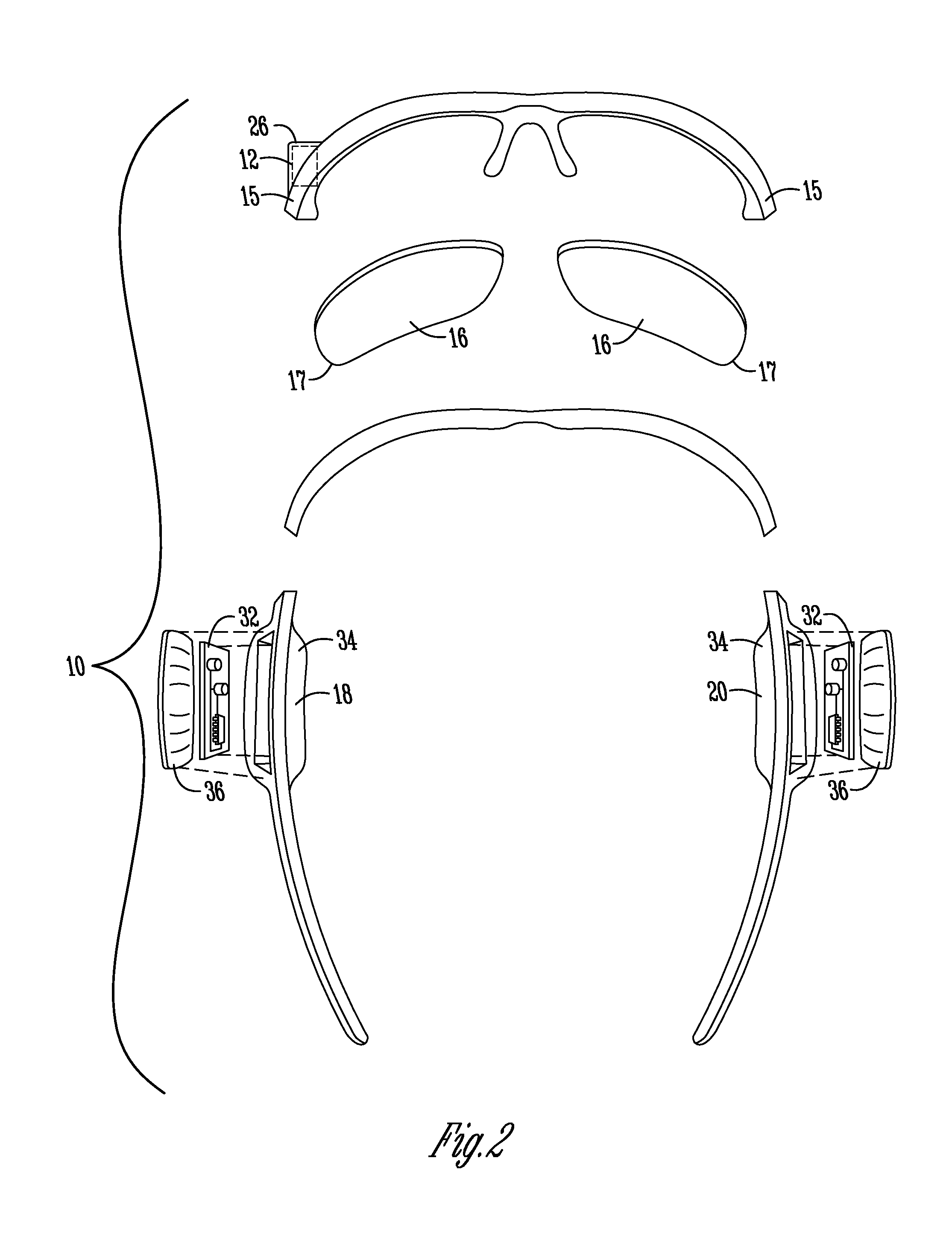
[0024]The device 10 includes an image sensor 12 with an associated housing 26. The image sensor 12 allows for acquiring video imagery. As shown in FIG. 1, the image sensor 12 is positioned on the side of the eyewear frame 14. The housing 26 is located between an outer lateral edge 17 of one of the lenses 16 and an outer lateral edge 15 of the frame. Although shown on the side of the eyewear frame 14, the image sensor may be otherwise positioned. Placing the image sensor 12 on the side of the frame 14 may be advantageous over placement in the center of the frame as this placement may be less likely to interfere with the use of a scope on a weapon.
[0025]Electronics 32 may be located within one or both of the temples 18, 20 of the eyeglasses 10 or within the frame 14. The electronics 32 may include hardware for storing imagery such on removable media (such as SD cards or other memory cards).
[0026]FIG. 2 provides an exploded view of the device 10 where electronics 32 are located in compartments 34 in the temples 18, 20 of the eyeglasses. Cover portions 36 are used to enclose the compartments 34. FIG. 3 illustrates the same device 10 as in FIG. 2, but in FIG. 3 the device 10 is fully assembled.
[0027]FIG. 4 is a block diagram of one embodiment of the device 10. As shown in FIG. 10, one or more image sensors 12 acquire(s) images which are communicated to an image processor 42 associated with a controller 44. The controller 44 is also operatively connected to user inputs 46 which may take the form of control buttons. The controller 44 is also operatively connected to indicator lights 48. The user inputs 46 and indicator lights 48 provide a user interface by which a user of the eyewear may interact with the eyewear in order to acquire imagery and record the imagery. An input/output interface 52 is also shown. This I/O interface is electrically connected to the controller 44. The I/O interface 52 may be a wired interface (such as a USB connector) or may be a wireless interface, such as a Bluetooth transceiver or a WiFi transceiver. Of course, other types of wired or wireless interfaces may be used. The controller 44 may also be in operative communication with storage media 50. The storage media may take different forms, examples including an SD card or micro SD card.
[0028]FIG. 5 illustrates one embodiment which allows adjustment of the aim and/or field of view. In order to allow adjustment of the aim and/or field of view of the lens 30, the lens 30 may be associated with known mechanical, optical, or digital means (not shown) for adjusting the aim/field of view of the lens 30. For example, the image sensor 12 and the lens 30 may be pivotally mounted within the camera enclosure 26 to allow left and right adjustment of the aim of the lens 30. As shown in FIG. 5, the image sensor 12 and the lens 30 are mounted on a pivot 60. A first adjustment button 62 and a second adjustment button 64 are located on the exterior of the camera enclosure 26. The first and second adjustment buttons are connected to a mechanical adjustment mechanism 66. The adjustment mechanism 66 is operable to change the position of the image sensor 12 and the lens 30 in response to actuation of the first and second adjustment buttons 62, 64, where each button 62, 64 corresponds to a different direction of adjustment.
[0029]FIG. 6 illustrates another embodiment in which multiple imaging devices are present. As shown in FIG. 6, an article of eyewear 110 is provided. There are camera enclosures 126 on each side of the eyewear and three imaging devices 112 are present. The imaging devices include a centrally located imaging device on the bridge of the eyeglass frame as well as imaging devices forward of the temple on each side of the eyewear frame. The present invention allows for video to be recorded from all imaging devices simultaneously. The present invention contemplates that imagery acquired from the imaging devices may be combined in various ways. For example, a panoramic view may be created by combining the different video streams. Alternatively, a composite view may be created which is picture-in-picture, or other types of composite views may be created. Alternatively, views may be combined to create or simulate a 3-D representation.
[0030]FIG. 7 illustrates another embodiment of the present invention. In FIG. 7, eyeglasses 110 are shown. The eyeglasses 10 have a single imaging device 112 within camera enclosure 126. The imaging device 112 is located forward of the temple, between the lens and the temple of the eyeglass frame 14.
[0031]FIG. 8 is a block diagram according to one aspect of the present invention. As shown in FIG. 8, an imaging device 110 is electrically connected to an intelligent control 102. The intelligent control 102 may be a processor or other type of intelligent control. The intelligent control 102 is operatively connected to a transceiver 104. The transceiver 104 may be a Bluetooth or a Wifi transceiver or other type of transceiver. In this embodiment the eyewear wirelessly communicates such as with a remote recording device 106. The remote recording device 108 includes a transceiver 108 which may operatively communicate with the transceiver 104. The transceiver 108 is operatively connected to a storage medium 110. Thus, video imagery acquired with the imaging device 100 within an article of eyewear may be streamed to a remote device 106 for recording. The remote device 106 may be a computer, a mobile device such as a cell phone, or other type of device. Software stored on a computer readable storage medium associated with the remote device 106 may provide functionality for recording the video, combining multiple video streams, editing video or other functionality.
[0032]In addition, a remote control device 112 is shown. The remote control device 112 includes a transceiver which may be in operative communication with the transceiver 104 of the eyewear. The remote control device 112 also includes user controls 116. The remote control device 112 allows a user to turn on and off video recording functionality remotely. This may be desirably in hunting as a user would not need to reach up to their eyewear to activate recording functionality.
[0033]FIG. 9 illustrates another embodiment where adjustment of the angle of the field of view such as may be achieved. In this embodiment, an adjustment mechanism 150 is shown which allows the angle of the imaging device 12 to be adjusted.
[0034]The present invention contemplates that the eyewear may be used in a number of different applications. These include, without limitation, archery, shooting (including rifle, shotgun, and pistol), bow hunting, fishing, skiing, recreational sporting activities, as a teaching aid in sports or medicine, as well as animal training.
[0035]Therefore, an article eyewear and related systems and methods have been described. Various different embodiments and aspects of the invention have been described. It is to be understood that the present invention contemplates numerous options, variations, and alternatives. These include variations in structure and function. It is to be further understood that different features from the different embodiments shown may be combined with features from other embodiments.

PUM

no PUM

Description & Claims & Application Information

We can also present the details of the Description, Claims and Application information to help users get a comprehensive understanding of the technical details of the patent, such as background art, summary of invention, brief description of drawings, description of embodiments, and other original content. On the other hand, users can also determine the specific scope of protection of the technology through the list of claims; as well as understand the changes in the life cycle of the technology with the presentation of the patent timeline. Login to view more.

Similar technology patents

Disposable medical-examination light

ActiveUS20090097236A1good visualizationeasy to use
Owner:UTAH MEDICAL PRODS

Patient positioning support structure

ActiveUS20120198625A1easy to useinexpensive to make
Owner:WARSAW ORTHOPEDIC INC

Classification and recommendation of technical efficacy words

  • easy to use

Laser assisted total joint arthroplasty

InactiveUS20090234360A1easy to use
Owner:ALEXANDER VLADIMIR

Enclosure for a portable hemodialysis system

ActiveUS20090114582A1easy to use
Owner:DEKA PROD LLP
Why Eureka
Try Eureka