Scroll compressor

a compressor and compressor technology, applied in the field of roller compressors, can solve the problems of deterioration of the oil supply from the high pressure region to the main ball bearing through the eccentric ball bearing, so as to enhance the reliabilities of the eccentric ball bearing and the main ball bearing

Active Publication Date: 2011-08-11
PANASONIC INTELLECTUAL PROPERTY MANAGEMENT CO LTD
View PDF5 Cites 6 Cited by
  • Summary
  • Abstract
  • Description
  • Claims
  • Application Information

AI Technical Summary

Benefits of technology

[0020]According to the scroll compressor of the present invention, since it is possible to control the supply of a very small amount of oil from the high pressure region to the back pressure chamber, it is possible to increase the amount of oil supplied to the eccentric ball bearing and the main ball bearing, and reliabilities of the eccentric ball bearing and the main ball bearing are enhanced.

Problems solved by technology

However, the conventional configuration has a problem that since oil is always supplied from a high pressure region to the back pressure chamber through the narrowed portion of the back pressure chamber oil-supply path, an amount of oil supplied from the high pressure region to a main ball bearing through an eccentric ball bearing is reduced, and reliabilities of the eccentric ball bearing and the main ball bearing are deteriorated.

Method used


Image

  • Scroll compressor
  • Scroll compressor
  • Scroll compressor

Examples


first embodiment

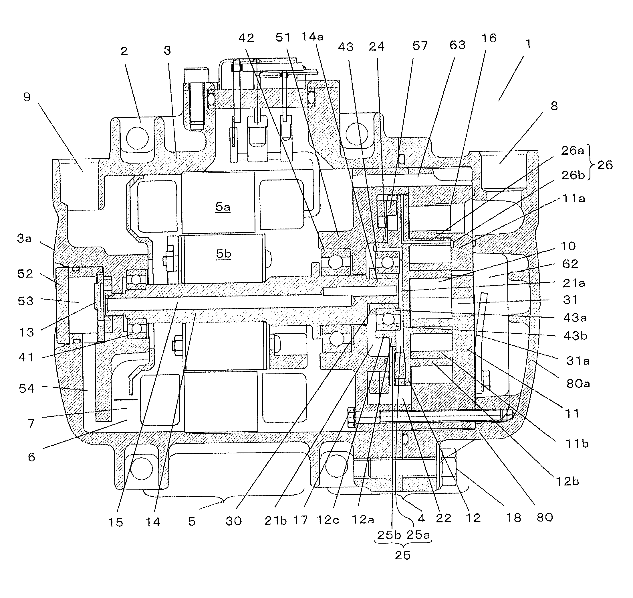
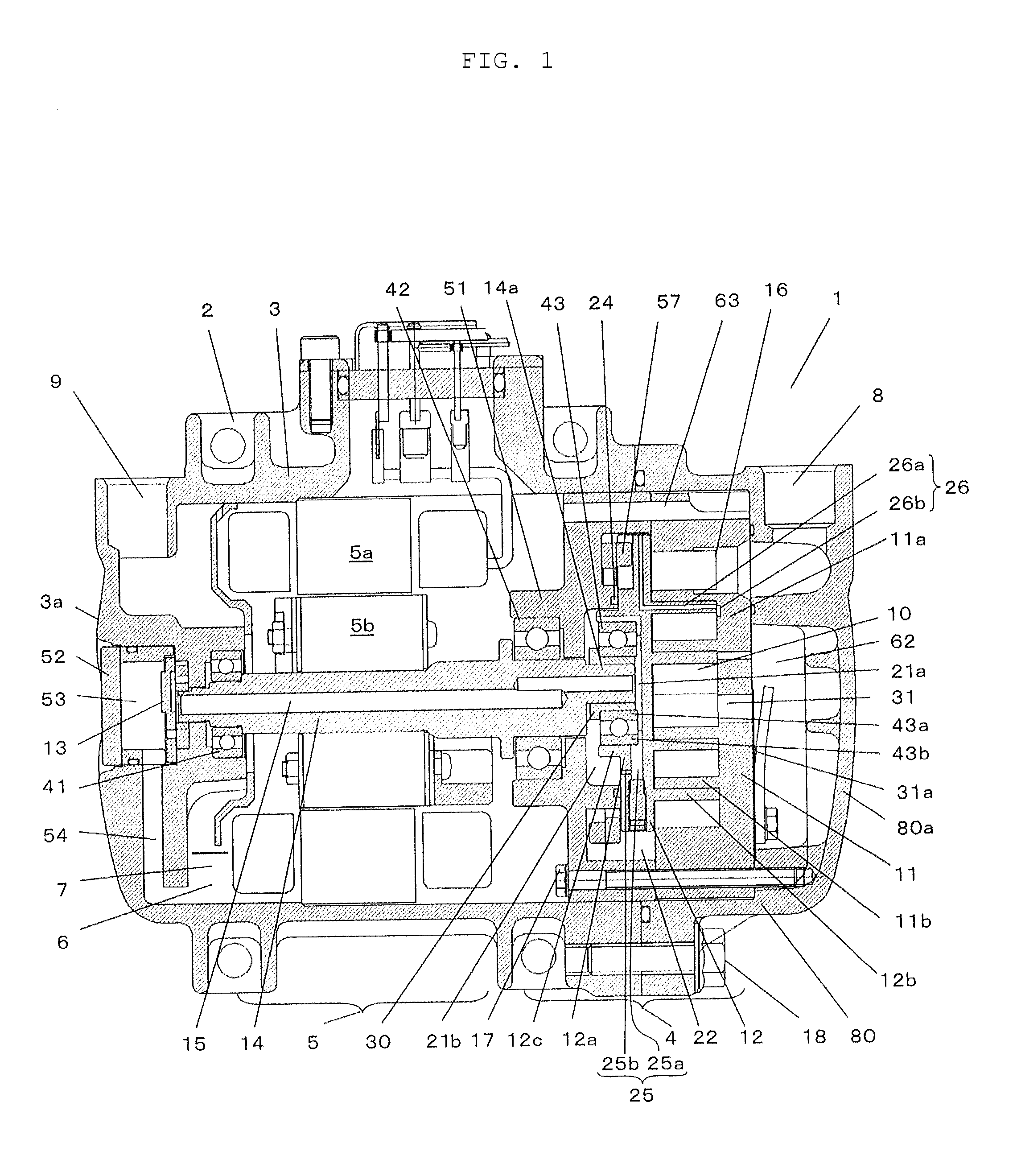
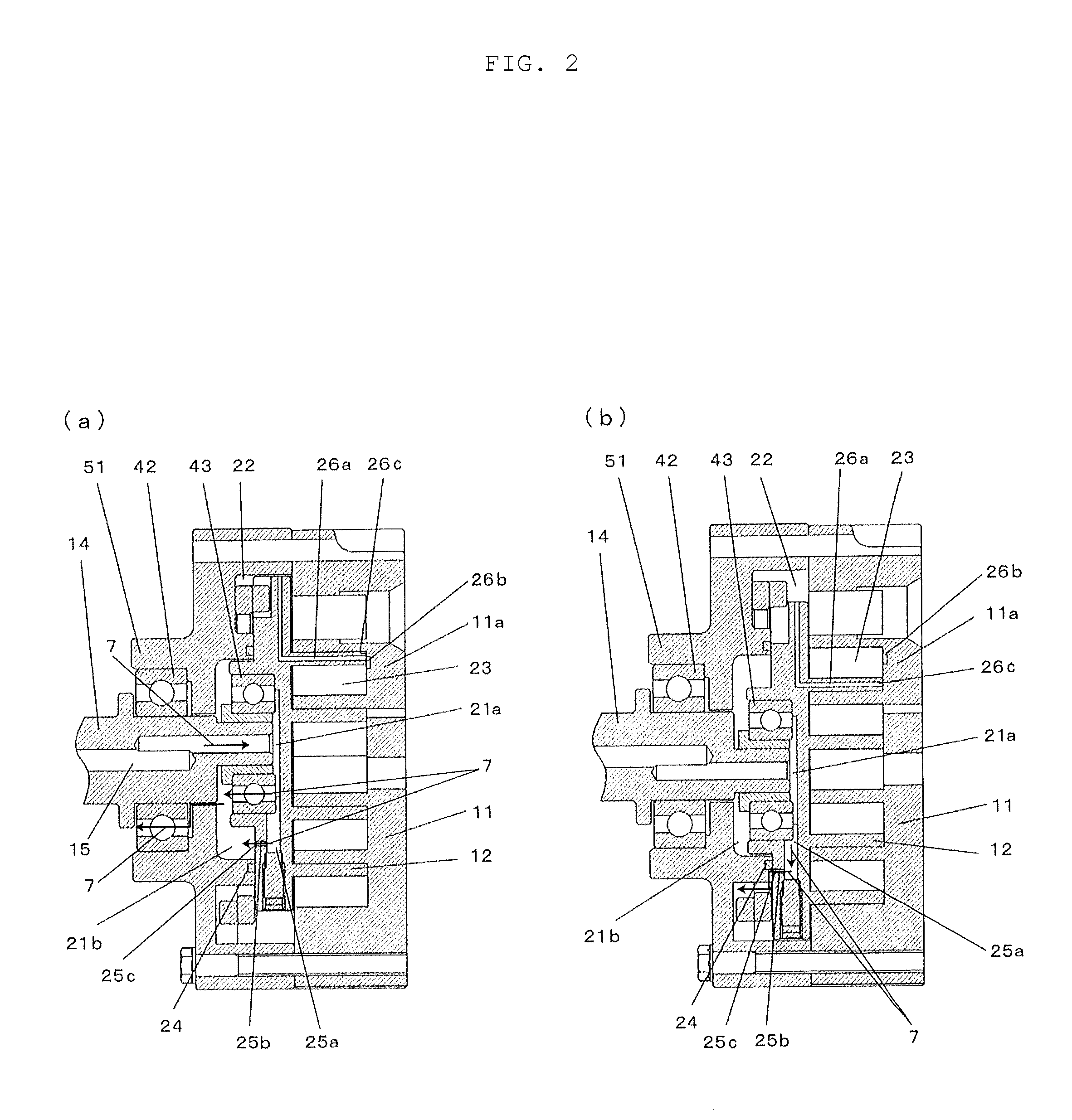
[0043]FIG. 1 is a sectional view of a scroll compressor according to a first embodiment of the present invention. FIG. 2 are enlarged sectional views of an essential portion of a compressing mechanism shown in FIG. 1. FIG. 3 are sectional views of an essential portion showing a combined state of an orbiting scroll and a fixed scroll of the scroll compressor. FIG. 4 are plan views of an essential portion showing a back surface of the orbiting scroll of the scroll compressor.

[0044]FIG. 1 shows a horizontal scroll compressor 1 which is horizontally disposed by a mounting leg 2. The mounting leg 2 is provided around a barrel portion of the scroll compressor 1. The scroll compressor 1 has a body casing 3, and a compressing mechanism 4 and a motor 5 which drives the compressing mechanism 4 are accommodated in the body casing 3. The scroll compressor 1 includes a liquid reservoir 6 in which lubricating oil 7 is stored. The motor 5 is driven by a motor-driving circuit (not shown). Working f...

second embodiment

[0076]FIG. 5 is a sectional view of a scroll compressor according to a second embodiment of the invention. FIG. 6 are enlarged sectional views of an essential portion showing operation of a compressing mechanism of the scroll compressor. The same configurations as those of the first embodiment are designated with the same symbols, and description thereof will be omitted.

[0077]In the second embodiment, the oil-supply passage 15 does not reach the eccentric shaft 14a, and an outlet of the oil-supply passage 15 is connected to a drive shaft oil-supply path 15a. The drive shaft oil-supply path 15a has an angle with respect to an axial direction of the drive shaft 14. A portion of a boundary between the drive shaft 14 and the eccentric shaft 14a on the side of the drive shaft 14 is notched by a flat surface 14b which is inclined with respect to the axial direction of the drive shaft 14, and an opening 15b of the drive shaft oil-supply path 15a is formed in the flat surface 14b.

[0078]Her...

third embodiment

[0088]FIG. 7 is a sectional view of a scroll compressor according to a third embodiment of the invention. FIG. 8 are enlarged sectional views of an essential portion of a compressing mechanism shown in FIG. 7. The same configurations as those of the first and second embodiments are designated with the same symbols, and description thereof will be omitted.

[0089]According to the third embodiment, in the scroll compressor in the second embodiment, the main ball bearing 42 has a shield. A material of a shield 42a is a stainless steel plate.

[0090]Here, flow of lubricating oil 7 in the compressing mechanism 4 will be described using FIG. 8.

[0091]As the orbiting scroll 12 orbits, lubricating oil 7 from the oil-supply passage 15 is supplied to the second high pressure region 21b through the drive shaft oil-supply path 15a.

[0092]In a state shown in FIG. 8(a), the one opening 25c of the back pressure chamber oil-supply path 25 is located on the side of the high pressure region 21 with respec...


PUM


Abstract

The present invention provides a scroll compressor in which the reliabilities of the eccentric ball bearing and the main ball bearing are enhanced by controlling an amount of oil supplied from the high pressure region to the back pressure chamber and an amount of oil from the high pressure region to the eccentric ball bearing and the main ball bearing. The scroll compressor includes a back pressure chamber oil-supply path 25 through which lubricating oil 7 is supplied from the high pressure region 21 to the back pressure chamber 22, and a compression chamber oil-supply path 26 through which lubricating oil 7 is supplied from the back pressure chamber 22 to the compression chamber, and the one opening 25c of the back pressure chamber oil-supply path 25 reciprocates, and comes into and comes out from the sealing member 24.

Description

TECHNICAL FIELD[0001]The present invention relates to a scroll compressor used for a cooling apparatus such as a cooling and heating air conditioner and a refrigerator, and for a heat pump hot water supply apparatus.BACKGROUND TECHNIQUE[0002]Conventionally, many manufacturers filed various similar patent applications relating to this kind of scroll compressor, and various compressors are actually utilized as compressors for domestic room air conditioners and compressors for refrigerators. Recently, the scroll compressors begin to be utilized as compressors for vehicular air conditioners.[0003]To lubricate a compressing mechanism of the compressor, there is a method for always supplying oil under a predetermined limitation by providing a narrowed portion in a back pressure chamber oil-supply path formed in an orbiting scroll as disclosed in patent document 1 for example.PRIOR ART DOCUMENT[0004][Patent Document 1] Japanese Patent Application Laid-open No. 2008-14283[0005]However, the ...

Claims


Application Information

Patent Timeline
Patent Type & Authority Applications(United States)
IPC IPC(8): F01C1/02
CPCF04C18/0215F04C18/0261F04C27/005F04C2240/60F04C28/265F04C29/021F04C29/023F04C27/007
Inventor YAMADA, SADAYUKIOGAWA, NOBUAKIABE, YOSHIFUMISAKUDA, ATSUSHIMORIMOTO, TAKASHI
Owner PANASONIC INTELLECTUAL PROPERTY MANAGEMENT CO LTD
Why Eureka
Try Eureka