Pulse burner and liquid heating cooker

Inactive Publication Date: 2009-04-09
PALOMA
View PDF48 Cites 5 Cited by
  • Summary
  • Abstract
  • Description
  • Claims
  • Application Information

AI Technical Summary

Benefits of technology

[0007]In the fryer described above, at the bottom portion of the oil vat which is located below the tail pipe, an area at the deep bottom referred to as a cold zone is formed, where the temperature of the oil becomes lower than the cooking temperature. By heaping oil sediment and oil deteriorated by oxidation in the cold zone, re-attachment of them to subjects to be cooked is prevented and quality of oil in a cooking zone on the upper side is maintained. However, the formation of this cold zone causes more increase in volume of the oil vat than the oil vat needs, so that increase in amount of oil to be used and increase in gas consumption amount necessary for heating are caused, and also increase in size and weight of the fryer is caused, whereby cost becomes expensive.
[0008]Therefore, an object of an aspect of the invention is to provide a pulse burner which leads to saving of the using amount of liquid such as oil and the gas consumption amount, and by which energy saving can expected; and a liquid heating cooker using the pulse burner.

Problems solved by technology

However, the formation of this cold zone causes more increase in volume of the oil vat than the oil vat needs, so that increase in amount of oil to be used and increase in gas consumption amount necessary for heating are caused, and also increase in size and weight of the fryer is caused, whereby cost becomes expensive.

Method used


Image

  • Pulse burner and liquid heating cooker
  • Pulse burner and liquid heating cooker
  • Pulse burner and liquid heating cooker

Examples


Embodiment Construction

[0014]An embodiment of the invention will be described below with reference to drawings.

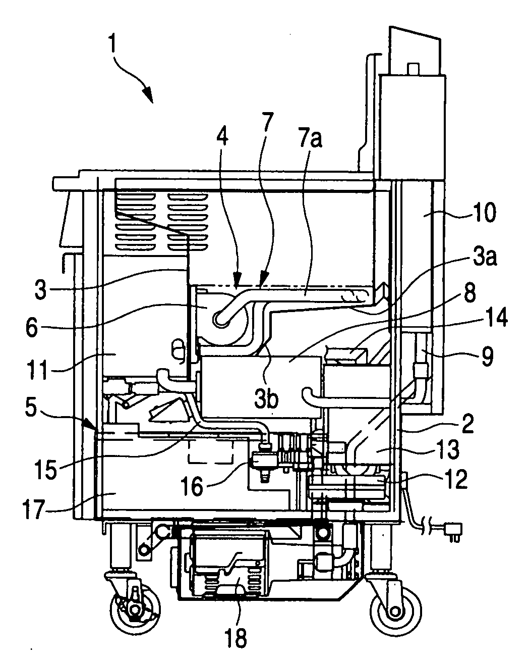
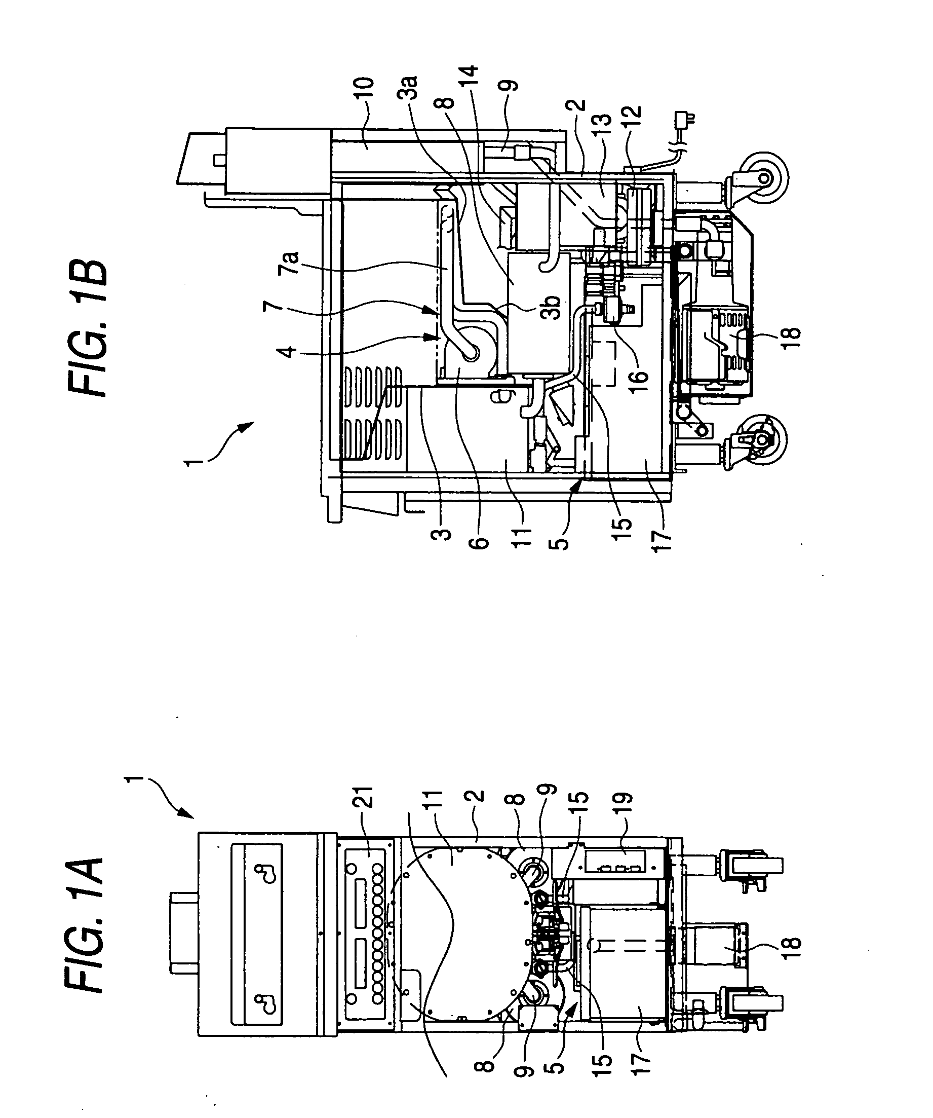
[0015]FIGS. 1A and 1B are explanatory views showing a fryer which is an example of a liquid heating cooker, in which FIG. 1 shows a front view and FIG. 1B shows a side view. A fryer 1 includes, in a housing 2, a pair of left and right oil vats 3 serving as a liquid vat which can store oil and partitioned in the center, a pulse burner 4 configured to heat the oil in each oil vat 3, and an oil cleaner 5 configured to filter the oil.

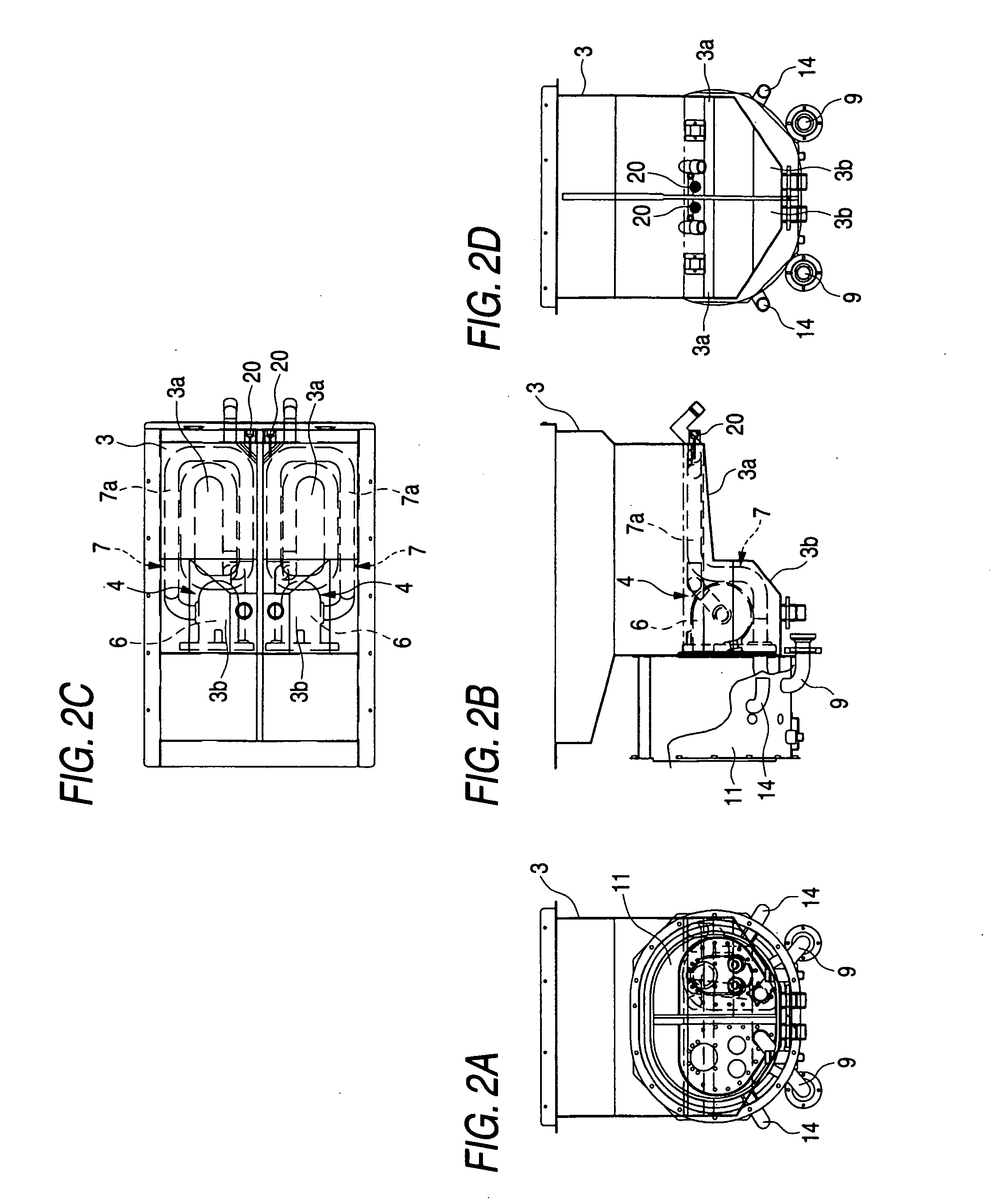
[0016]The pulse burner 4 includes a combustion-exhaust system including: a combustion chamber 6 provided in each oil vat 3 and configured to combust mixed gas of fuel gas and combustion air; a tail pipe 7 through which combustion gas from the combustion chamber 6 passes; a de-coupler 8, 8 connected to the downstream side of the tail pipe 7 and provided on both sides of the oil vat 3; and an exhaust duct 9 which is connected to the downstream side of the de-coupler 8, 8 a...


PUM


Abstract

A pulse burner includes: a combustion chamber provided in a liquid vat capable of storing liquid; a tail pipe that is connected to the combustion chamber and has a heat exchanging portion located in the liquid vat and bent in a predetermined shape; and a mixing chamber which communicates with the combustion chamber and to which fuel gas and combustion air is allowed to be supplied. When mixed gas including the fuel gas and the combustion gas is exploded and combusted, the combustion exhaust gas is exhausted through the tail pipe to allow heat exchange with the liquid, and the mixed gas is inhaled from the mixing chamber into the combustion chamber. At least the heat exchanging portion of the tail pipe is bent on a substantially horizontal plane.

Description

CROSS-REFERENCE TO RELATED APPLICATIONS[0001]This application is based upon and claims priority from Japanese Patent Application No. 2007-262487 filed on Oct. 5, 2007, the entire contents of which are incorporated herein by reference.BACKGROUND OF THE INVENTION[0002]1. Field of the Invention[0003]The present invention relates to: a pulse burner used in a liquid heating cooker such as a fryer and configured to explode and combust mixed gas of fuel gas and combustion air and feed combustion exhaust gas into a tail pipe connected to the combustion chamber thereby to enable heat-exchange with external liquid; and a liquid heating cooker using the pulse burner as a heating unit.[0004]2. Description of Related Art[0005]A fryer serving as an example of a liquid heating cooker is described in JP-A-2002-223953, for example. The fryer includes, at an upper part in a housing, an oil vat for storing cooking oil therein, and a pulse burner for heating the oil stored in the oil vat. The oil store...

Claims


Application Information

Patent Timeline
IPC IPC(8): A47J37/12F23C15/00
CPCA47J37/1252F23C15/00F23C3/004F23C3/002
Inventor CHIKAZAWA, HIDEOHAYAKAWA, TSUNEYASUKIJIMOTO, HIDEKI
Owner PALOMA
Why Eureka
Try Eureka