Relief valve device

a valve device and relief valve technology, applied in the direction of fluid pressure control, process and machine control, instruments, etc., can solve the problem of difficulty in realizing relief operation with intermediate hydraulic pressure, and achieve the effect of increasing the amount of oil supplied

Active Publication Date: 2017-02-16
YAMADA SEISAKUSHO KK
View PDF4 Cites 5 Cited by
  • Summary
  • Abstract
  • Description
  • Claims
  • Application Information

AI Technical Summary

Benefits of technology

[0011]A second embodiment of the present invention solves the problems by the relief valve device according to the first embodiment, in which the valve chamber has a first valve passage portion, and a second valve passage portion having the orifice, the valve body has a first valve portion and a second valve portion arranged in an axial direction, the oil control valve supplies oil to the second valve passage portion, the first valve portion is disposed in the first valve passage portion, the second valve portion is disposed in the second valve passage portion, and oil is supplied to the second valve passage portion through the oil control valve while an amount of oil is increased and decreased steplessly, and the supplied oil is discharged from the orifice.
[0012]A third embodiment of the present invention solves the problems by the relief valve device according to the first embodiment, in which the valve chamber has a first valve passage portion having the orifice, and a second valve passage portion, the valve body has a first valve portion and a second valve portion arranged in an axial direction, the oil control valve supplies oil to the first valve passage portion, the first valve portion is disposed in the first valve passage portion, the second valve portion is disposed in the second valve passage portion, and oil is supplied to the first valve passage portion through the oil control valve while an amount of oil is increased and decreased steplessly, and the supplied oil is discharged from the orifice.
[0013]A fourth embodiment of the present invention solves the problems by the relief valve device according to the first embodiment, in which an oil inlet port that applies pressure to the valve body is formed on a front end side of the valve chamber, an inlet port close to the oil control valve and the orifice are formed on a rear end side of the valve chamber, and the oil control valve is positioned on the rear end side and an upstream side of the valve chamber so as to supply oil while increasing and decreasing an amount of oil steplessly, and to discharge the supplied oil from the orifice.
[0014]A fifth embodiment of the present invention solves the problems by the relief valve device according to the first or second embodiment, in which a solenoid valve is used as the oil control valve. A sixth embodiment of the present invention solves the problems by the relief valve device according to the third or fourth embodiment, in which a solenoid valve is used as the oil control valve. A seventh embodiment of the present invention solves the problems by the relief valve device according to the first or second embodiment, in which a smallest cross-sectional area of a passage to the valve chamber in a fully open state of the oil control valve is larger than a smallest cross-sectional area of the orifice. An eighth embodiment of the present invention solves the problems by the relief valve device according to the third or fourth embodiment, in which a smallest cross-sectional area of a passage to the valve chamber in a fully open state of the oil control valve is larger than a smallest cross-sectional area of the orifice.
[0015]A ninth embodiment of the present invention solves the problems by the relief valve device according to the first or second embodiment, in which the oil control valve is fully closed in a rotation speed range near a low rotation speed range and an idling rotation speed range of an engine. A tenth embodiment of the present invention solves the problems by the relief valve device according to the third or fourth embodiment, in which the oil control valve is fully closed in a rotation speed range near a low rotation speed range and an idling rotation speed range of an engine. An eleventh embodiment of the present invention solves the problems by the relief valve device according to the first or second embodiment, in which when a rotation speed increases within a medium rotation speed range of an engine, the oil control valve increases the amount of oil supplied to the valve chamber steplessly. A twelfth embodiment of the present invention solves the problems by the relief valve device according to the third or fourth embodiment, in which when a rotation speed increases within a medium rotation speed range of an engine, the oil control valve increases the amount of oil supplied to the valve chamber steplessly. A thirteenth embodiment of the present invention solves the problems by the relief valve device according to the first or second embodiment, in which when a rotation speed increases within a high rotation speed range of an engine, the oil control valve decreases an amount of oil supplied to the valve chamber steplessly. A fourteenth embodiment of the present invention solves the problems by the relief valve device according to the third or fourth embodiment, in which when a rotation speed increases within a high rotation speed range of an engine, the oil control valve decreases an amount of oil supplied to the valve chamber steplessly.
[0016]According to the present invention, the relief valve device includes a valve body that opens and closes the relief discharge port while moving inside the valve chamber of the housing; a relief valve including an elastic member that elastically biases the valve body in a direction in which the valve body closes the relief discharge port; and an oil control valve that controls the supply of oil into the valve chamber, wherein an inlet port for the oil supplied from the oil control valve and the orifice are configured such that oil can always circulate in the valve chamber. Due to this, it is possible to discharge oil with an appropriate discharge pressure in low, medium, and high rotation speed ranges of an engine.

Problems solved by technology

In this conventional technique, the relief pressure can be changed between two values only, and it is difficult to realize a relief operation with an intermediate hydraulic pressure between the relief operation with a low hydraulic pressure and the relief operation with a high hydraulic pressure.

Method used


Image

  • Relief valve device
  • Relief valve device
  • Relief valve device

Examples


first embodiment

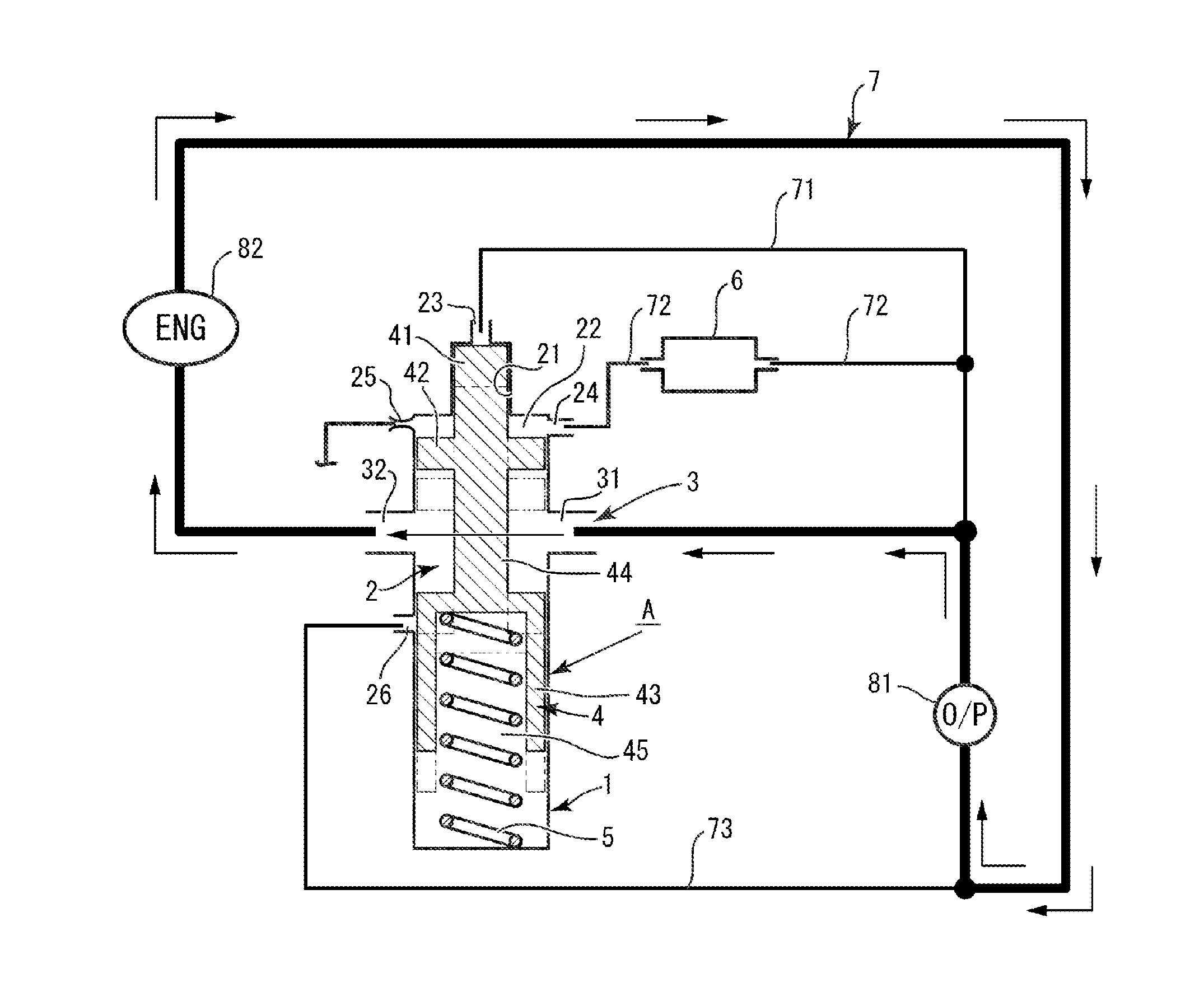
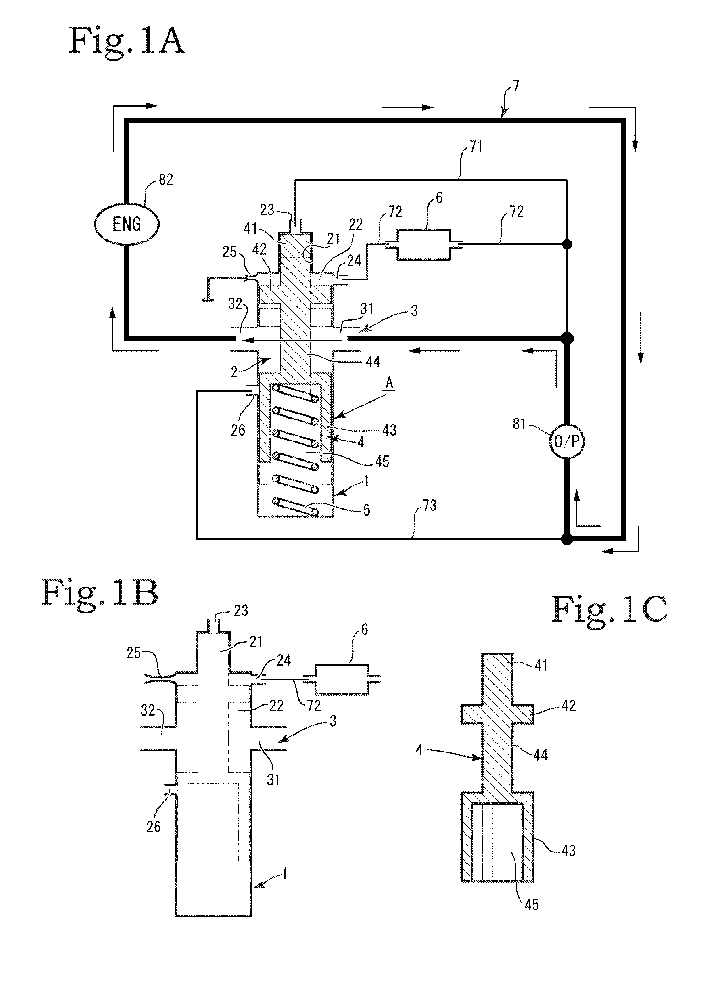
[0028]Hereinafter, embodiments of the present invention will be described based on the drawings. A configuration of the present invention has a plurality of embodiments and mainly includes a relief valve A and an oil control valve 6. The relief valve A is incorporated into an oil circulation circuit 7. An oil pump 81 and an engine 82 are provided in the oil circulation circuit 7 (see FIG. 1A). Hereinafter, the present invention will be described.

[0029]The relief valve A includes a housing 1, a valve body 4, an elastic member 5, and the like (see FIG. 1A). A valve chamber 2 is formed in the housing 1 (see FIG. 1B). The valve chamber 2 is a chamber serving as a passage through which the valve body 4 moves. Further, a front end and a rear end of the housing 1 are set for the sake of convenience. A valve chamber 2 described later is included in the housing 1 and the front and rear ends of the valve chamber 2 are the same as the front and rear ends of the housing 1. Moreover, it is assum...

second embodiment

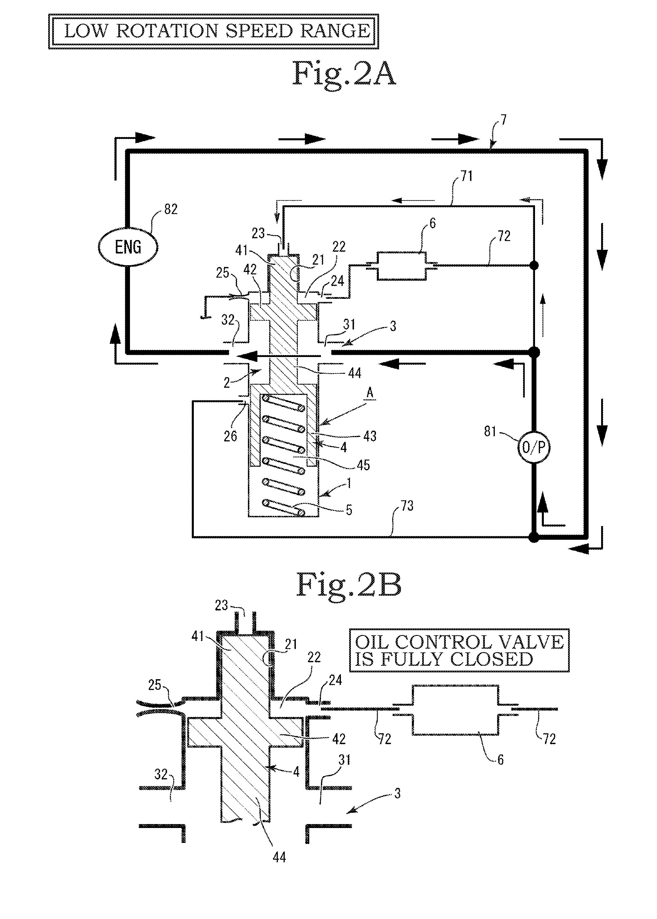
[0056]In the second embodiment, in a state in which the second valve portion 42 of the valve body 4 has reached the front end portion of the second valve passage portion 22, the front end of the first valve portion 41 does not make contact with the front end portion of the first valve passage portion 21, and a gap is formed therebetween. Due to the gap, the orifice 25 and the first inlet port 23 always communicate with each other inside the first valve passage portion 21. Moreover, the relief oil supplied from the oil control valve 6 can pass from the first inlet port 23 through the first valve passage portion 21 of the valve chamber 2 and flow into the orifice 25.

[0057]In the second embodiment, similarly to the first embodiment, the relief oil flowing from the first and second inlet ports 23 and 24 into the first and second valve passage portions 21 and 22 of the valve chamber 2 applies hydraulic force in a direction in which the valve body 4 moves toward the rear end side of the v...

third embodiment

[0061]The orifice 25 and the second integrated inlet port 28 for the oil supplied from the oil control valve 6 are formed on the rear end side of the valve chamber 2. That is, the orifice 25 and the second integrated inlet port 28 for the oil supplied from the oil control valve 6 are positioned on the side of the valve chamber 2 on which the third valve portion 43 of the valve body 4 is disposed. In the third embodiment, the pressure of oil in the integrated passage portion 212 on the upstream side of the formation position of the orifice 25 increases as the amount and the velocity of oil supplied from the oil control valve 6 increase. Thus, even when the hydraulic force based on the oil on the side of the first integrated inlet port 27 is applied to the valve body 4, the movement of the valve body 4 is controlled to be slowed by the resistance based on the hydraulic pressure of the oil on the side of the second integrated inlet port 28.

[0062]The movement is controlled by the oil co...


PUM


Abstract

Provided is a relief valve device including: a housing (1) including a valve chamber (2), an orifice (25), and a relief discharge port (26); a valve body (4) that opens and closes the relief discharge port (26) while moving inside the valve chamber (2) of the housing (1); a relief valve (A) including an elastic member (5) that elastically biases the valve body (4) in a direction in which the valve body (4) closes the relief discharge port (26); and an oil control valve (6) that controls the supply of oil into the valve chamber (2), wherein an inlet port for the oil supplied from the oil control valve (6) and the orifice (25) are configured such that oil can always circulate in the valve chamber (2).

Description

BACKGROUND OF THE INVENTION[0001]1. Field of the Invention[0002]The present invention relates to a relief valve device capable of allowing an oil pump of a vehicle engine or the like to discharge oil with an appropriate discharge pressure in low, medium, and high rotation speed ranges of the engine.[0003]2. Description of the Related Art[0004]Conventionally, there are various types of relief valve devices each provided in an oil circulation circuit that supplies oil to an engine and supplying oil with a hydraulic pressure appropriate for low, medium, and high rotation speed ranges of the engine. Japanese Patent Application Publication No. 2010-238205 discloses an example of a relief valve device of this type.[0005]The invention disclosed in Japanese Patent Application Publication No. 2010-238205 will be described briefly. In the following description the reference numerals used in Japanese Patent Application Publication No. 2010-238205 are used as they are by putting the same in bra...

Claims


Application Information

Patent Timeline
Patent Type & Authority Applications(United States)
IPC IPC(8): F01M1/16F01M1/02G05D16/02F16K31/06F16K17/04
CPCF01M1/16F16K31/06F01M1/02G05D16/02F16K17/04F16K17/0473F16K17/065
Inventor WATANABE, TAKATOSHIMIYAJIMA, JUNICHIKANEKO, ATSUSHIKATO, YUYA
Owner YAMADA SEISAKUSHO KK
Why Eureka
Try Eureka