Spinal fixation assembly with intermediate element

Inactive Publication Date: 2011-08-11
INGENIUM
View PDF45 Cites 95 Cited by
  • Summary
  • Abstract
  • Description
  • Claims
  • Application Information

AI Technical Summary

Benefits of technology

[0019]According to another aspect of the invention, another method is provided for locking the relative positions of a rod and a screw. The method may include placing a rod in a body at least partially encompassing a screw and an intermediate element located above the screw, wherein the intermediate element has a non-circular bottom profile and the body ...

Problems solved by technology

One of the main challenges associated with internal spinal fixati...

Method used


Image

  • Spinal fixation assembly with intermediate element
  • Spinal fixation assembly with intermediate element
  • Spinal fixation assembly with intermediate element

Examples


Embodiment Construction

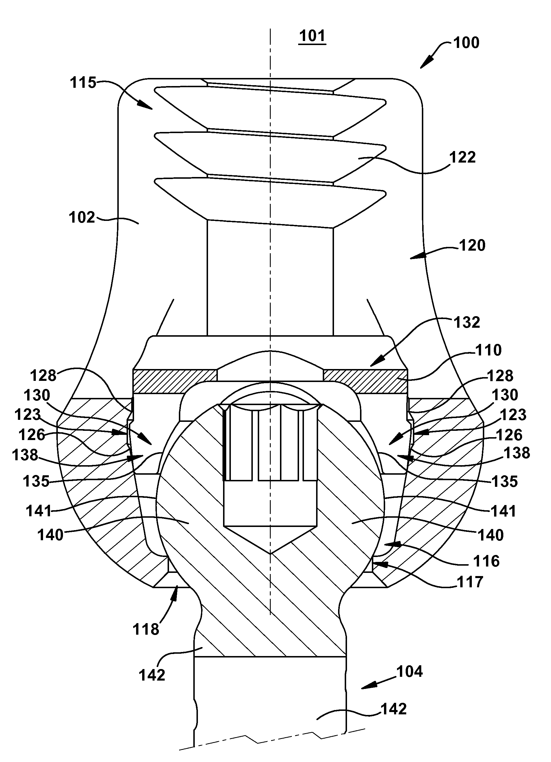
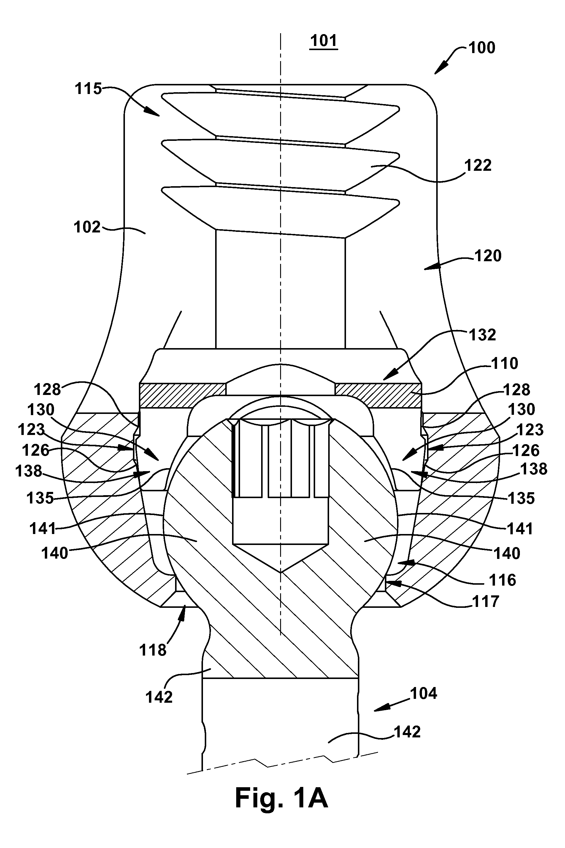
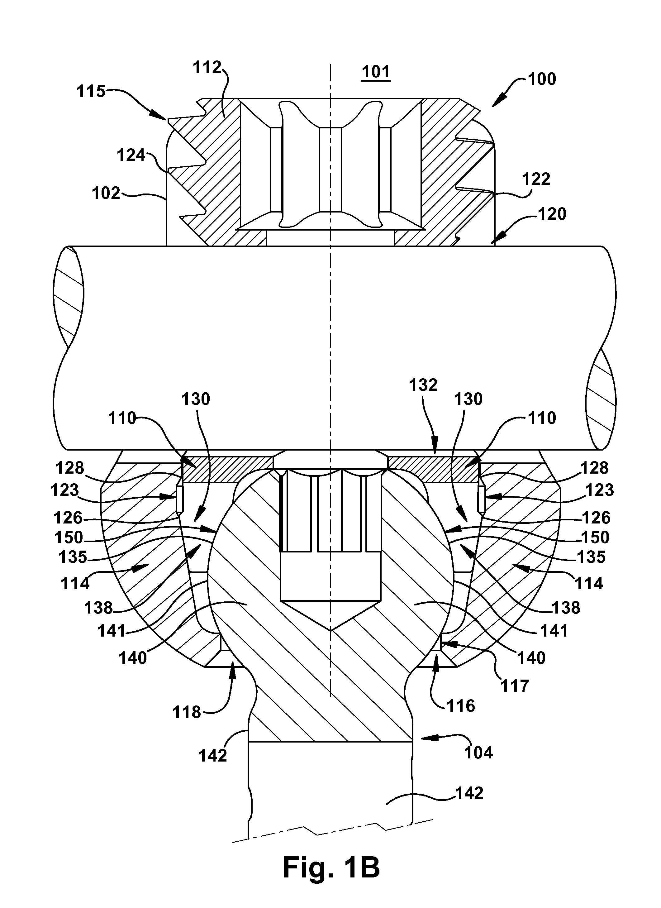
[0033]The invention relates to a novel locking mechanism and method for locking the relative positions of a rod and a screw. The locking mechanism provides an improved lock between the rod and the screw head. The locking element includes a body and intermediate element. The intermediate element is located between the rod and the head of a screw and may directly contact both the rod and screw when the locking mechanism is in a final locking position. The intermediate element preferably has a non-circular shape such that at least one non-contact area exists when the intermediate element is in contact with the head of the screw and the locking mechanism is fully engaged. To engage the locking mechanism, the rod may be preferably urged downward toward the bottom of the body, thereby forcing the intermediate element toward the bottom of the body. The body may also have at least one structure defining one or more distinct temporary stopping points for the intermediate element above the fi...


PUM


Abstract

A novel locking mechanism including a body and intermediate element and a method for locking the relative positions of a rod and a screw. The intermediate element is adapted to receive a rod and a head of a screw and is located between the rod and the head of the screw. The intermediate element has a non-circular shape such that at least one large non-contact area exists when the intermediate element is in contact with the head of the screw and the locking mechanism is fully engaged. The body is adapted to maintain the orientation of the non-circular intermediate element with respect to the body. The body also has at least one structure defining at least one distinct temporary stopping point for the intermediate element above the final locking position.

Description

FIELD OF THE INVENTION[0001]The present invention relates generally to prostheses for treating spinal pathologies, and more specifically to spinal fixation assemblies including a locking mechanism for holding a screw and a stabilization rod.BACKGROUND OF THE INVENTION[0002]Various methods of spinal immobilization have been used in the treatment of spinal instability and displacement. The most common treatment for spinal stabilization is immobilization of the joint by surgical fusion, or arthrodesis. This has been known for almost a century. In many cases, however, pseudoarthrosis occurs, particularly in cases involving fusion across the lumbosacral articulation and when more than two vertebrae are fused together. Early in the century, post operative external immobilization, such as through the use of splints and casts, was the favored method of spinal fixation. As surgical techniques became more sophisticated, various new methods of internal and external fixation were developed.[000...

Claims


Application Information

Patent Timeline
IPC IPC(8): A61B17/86
CPCA61B17/7037
Inventor WALSH, DAVID A.RANDOL, DAVID S.
Owner INGENIUM
Why Eureka
Try Eureka