Electronic throttle control pedal assembly with hysteresis

a technology of electronic throttle control and pedal assembly, which is applied in the direction of mechanical control devices, process and machine control, instruments, etc., can solve the problems of control removal and simulation, and achieve the effect of increasing the resistance to the pedal depression and increasing the resistan

Inactive Publication Date: 2011-08-18
KSR IP HLDG
View PDF9 Cites 19 Cited by
  • Summary
  • Abstract
  • Description
  • Claims
  • Application Information

AI Technical Summary

Benefits of technology

[0010]One advantage of the present invention is that the electronic throttle control pedal assembly is provided with a hysteresis generating device which progressively increases the resistance to the pedal depression. The progressive increase of resistance as the pedal is depressed provides the driver with a more realistic feel of a mechanical pedal assembly. Other features and advantages of the present invention will be readily understood as the same becomes better understood upon reading the subsequent description when considered in connection with the accompanying drawings.

Problems solved by technology

A significant drawback of these pedal assemblies is that the removal of the physical connection of the pedal to the vehicle control removes the resistance or “pedal feel” that a driver is typically accustomed to sense during vehicle operation.
However, although the compression of the spring resists depression, the springs do not simulate the “pedal feel” of a conventional pedal assembly which can be disorienting to a driver as the driver does not feel connected to the vehicle controls.

Method used


Image

  • Electronic throttle control pedal assembly with hysteresis
  • Electronic throttle control pedal assembly with hysteresis
  • Electronic throttle control pedal assembly with hysteresis

Examples


first embodiment

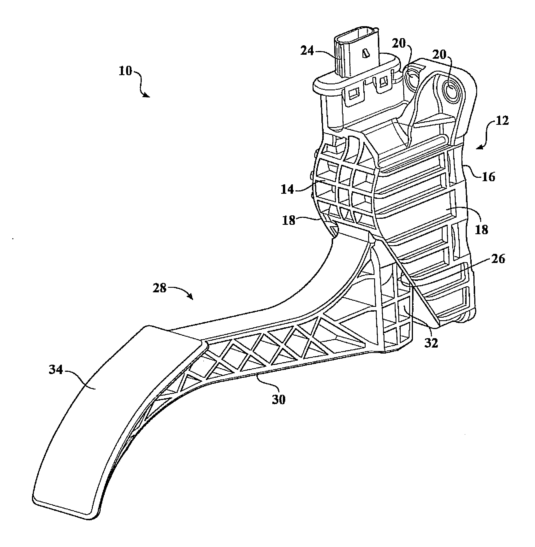
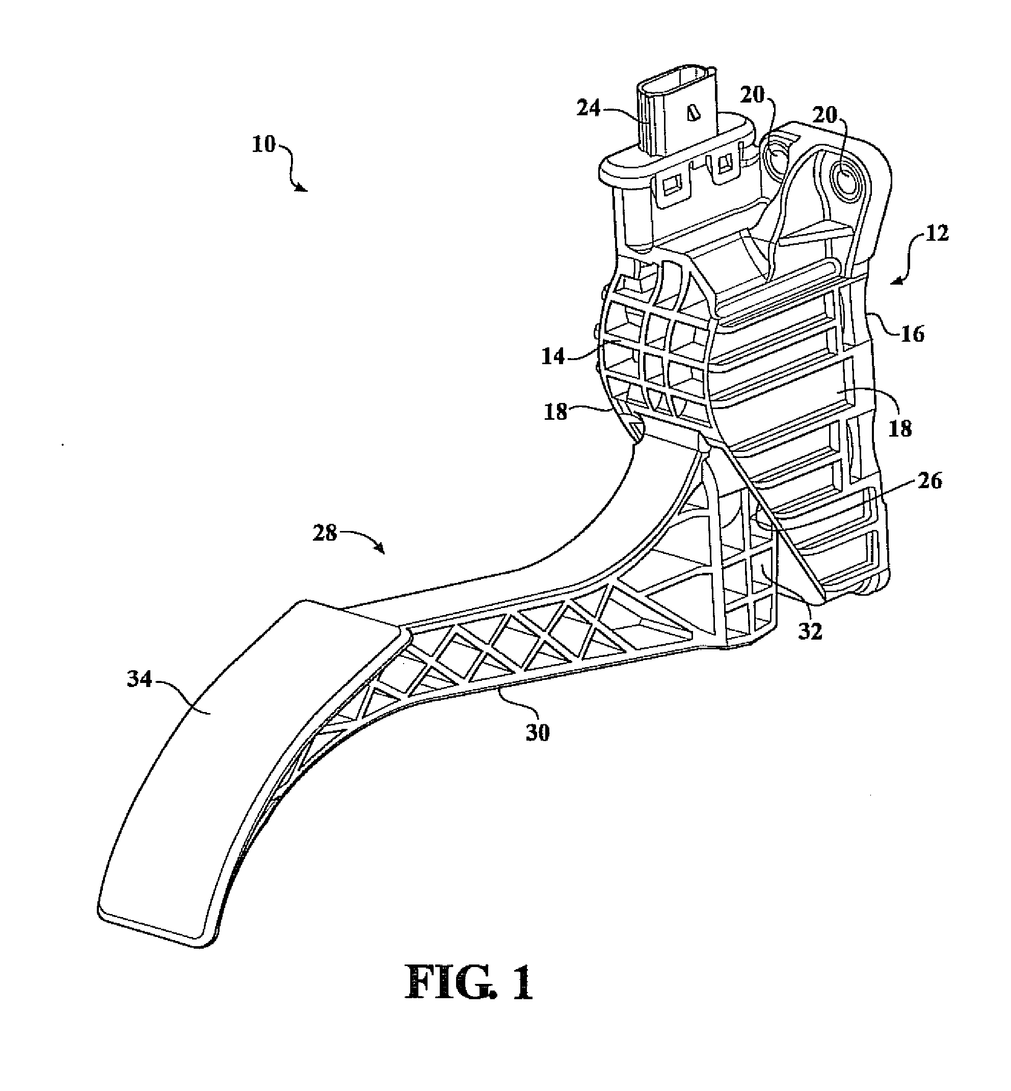
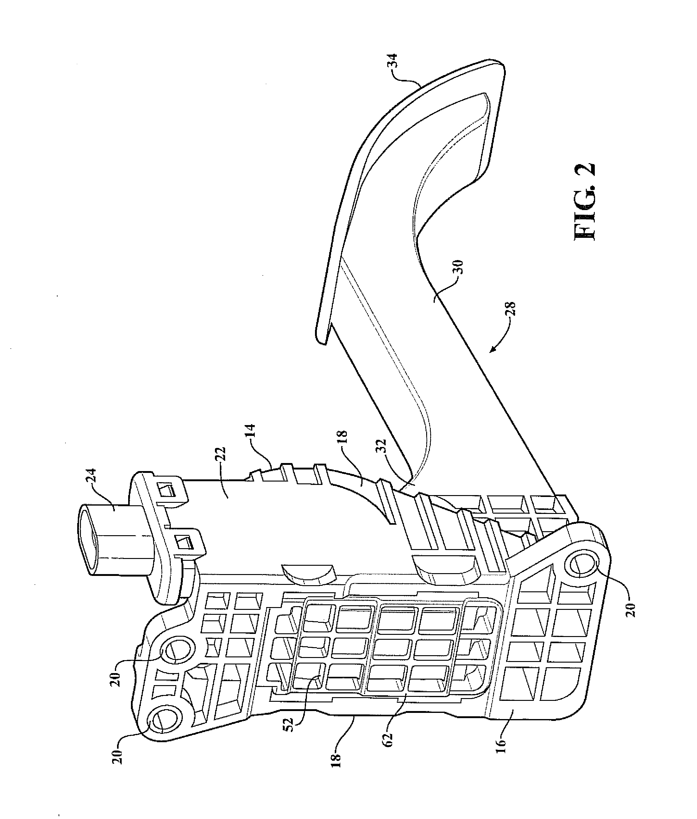
[0023]Referring to FIGS. 1-6, an electronic throttle control pedal assembly for generating hysteresis to simulate the feel of a conventional mechanical pedal assembly is generally illustrated at 10. The pedal assembly includes a housing bracket 12 for securing the pedal assembly 10 to a portion of the automotive vehicle. In the illustrated example, the housing bracket 12 is attached to a portion of the firewall (not shown) of the vehicle.

[0024]The housing bracket 12 includes a front wall 14, an opposite rear wall 16, and a pair of opposing side walls 18 which traverse the front wall 14 and the rear wall 16. The rear wall 16 of the housing bracket 12 is formed of a generally planar surface for attaching the housing bracket 12 to the firewall (not shown) of the vehicle. The rear wall 16 includes at least one aperture 20 for securing the housing bracket 12 to the vehicle using any known fastener or attaching means to secure one object to another illustratively including bolting, screwi...

second embodiment

[0043]With reference to FIGS. 7-9, an alternative embodiment of the inventive pedal assembly having the hysteresis generating device is generally illustrated at 210. the pedal assembly 210 is an organ style pedal assembly which mounts to the floor (not shown) of the vehicle. The pedal assembly 210 includes a pedal arm 212 and a mounting bracket 214.

[0044]The pedal arm 212 includes a pedal pad 216 optionally formed of an isometric material so as to provide friction between the pedal pad 216 and a driver's foot. The pedal arm 212 connects to the mounting bracket 214 at a lower edge by a living hinge 218 which pivotally connects the pedal arm 212 to the housing bracket 214. An extension 220 extends outwardly from the pedal arm on a side opposite the pedal pad 216. The extension 220 extends through an opening 222 formed in the housing bracket 214 and abuts a guide portion 224. The pedal arm 212 pivots about the living hinge 218 and is guided along a predetermined pedal path by the inter...


PUM


Abstract

An electronic throttle control pedal assembly includes a housing having a cavity formed therein which is mounted to the vehicle. A hub is rotatably attached to the housing within the cavity. The hub includes at least a portion having a circumferential outer wall having an engagement portion. The pedal assembly includes a pedal arm having a pedal pad positioned at one end, and an opposite end operatively attached to the hub such that depression of the pedal pad rotates the hub.

Description

CROSS-REFERENCE TO RELATED APPLICATIONS[0001]This application claims priority of U.S. Provisional Patent Application Ser. No. 61 / 305,372 filed Feb. 17, 2010, which is hereby incorporated by reference.FIELD OF THE INVENTION[0002]The present invention relates to an electronic throttle control pedal assembly and, more particularly, to a pedal assembly having a hysteresis generating device.BACKGROUND OF THE INVENTION[0003]It is known to use pedal assemblies having position sensors to produce a “fly-by-wire” type pedal assembly for vehicle control such as brake and throttle operation rather than relying on a physical connection between the pedal and the vehicle control. A significant drawback of these pedal assemblies is that the removal of the physical connection of the pedal to the vehicle control removes the resistance or “pedal feel” that a driver is typically accustomed to sense during vehicle operation. As such, it is desirable to stimulate the feel of a mechanical pedal assembly.[...

Claims


Application Information

Patent Timeline
Patent Type & Authority Applications(United States)
IPC IPC(8): G05G1/30
CPCG05G1/30G05G5/03Y10T74/20528Y10T74/2054Y10T74/20888Y10T74/20534
Inventor O'NEILL, DAN
Owner KSR IP HLDG
Why Eureka
Try Eureka