Electric wire with terminal and method of manufacturing the same

a technology of terminals and electric wires, applied in the direction of electrically conductive connections, cable junctions, deformation formation, etc., can solve the problems of reducing the reliability of mechanical connection strength (connection strength) and electrical connection (contact resistance), increasing the number of processes and costs, and reducing the mechanical connection strength between the terminal and the conductor

Active Publication Date: 2011-08-18
HITACHI METALS LTD
View PDF4 Cites 34 Cited by
  • Summary
  • Abstract
  • Description
  • Claims
  • Application Information

AI Technical Summary

Benefits of technology

[0044]FIG. 3 is a schematic partial cross sectional view showing a connecting portion for explaining an effect of the invention when a cross-sectional area of a first conductor is smaller than that of a second conductor;
[0045]FIG. 4 is a perspective view showing an electric wire with terminal in another embodiment of the invention in a state before connection;
[0046]FIG. 5 is a perspective view showing the electric wire with terminal in the other embodiment of the invention in a state that the end portion of the conductor is divided into two before the connection;
[0047]FIG. 6 is a perspective view showing the electric wire with terminal in the other embodiment of the invention in a state after connection;
[0048]FIG. 7 is a perspective view showing an electric wire with terminal in Comparative

Problems solved by technology

However, JP-A 2003-117666 and JP-A 7-326412 in which the compression joint is used have a problem that it becomes difficult to exposed an active surface by destroying an oxide film formed on a surface of a conductor using plastic deformation at the time of compression as the cross-sectional area of the conductor increases (e.g., a cross-sectional area of 20 mm2 or more) especially when the conductor is formed by twisting plural strands together, which result in a decrease in reliability of mechanical connection strength (connection strength) and electrical connection (contact resistance).
As one of such compression joint methods, there is a method in which the compression joint is conducted after a special treatment such as soldering is performed on an edge of a conductor in order to improve reliability of mechanical connection strength and electrical connection, however, there is a problem that the number of processes and the cost greatly increase.
Meanwhile, in the ultrasonic compression bonding method (between a terminal and a conductor) using an ultrasonic compression bonding apparatus described in JP-A 2003-117666, there is a problem that, when, e.g., an Al or Al alloy conductor (e.g., a conductor having a cross-sectional area of 20 mm2 or more) is bonded to a terminal formed of Cu or a Cu alloy, mechanical connection strength between the terminal and the conductor decreases under a thermal cycle environment due to a decrease in mechanical grip force caused by a thermal expansion coefficient difference between Cu and Al, accordingly, the reliability of the electrical connection between the terminal and the conductor also decreases.
In addition, when an open barrel-shaped crimp-type terminal described in FIGS. 6 to 8 of JP-A 2003-117666 is used and an Al or Al ally conductor having a large cross-sectional area is bonded to an Al or Al alloy terminal, it is not possible to impart sufficient crimp force to an Al member having small deformation resistance, and thus, a problem in reliability of mechanical connection strength and electrical connection occurs.

Method used


Image

  • Electric wire with terminal and method of manufacturing the same
  • Electric wire with terminal and method of manufacturing the same
  • Electric wire with terminal and method of manufacturing the same

Examples


example 1

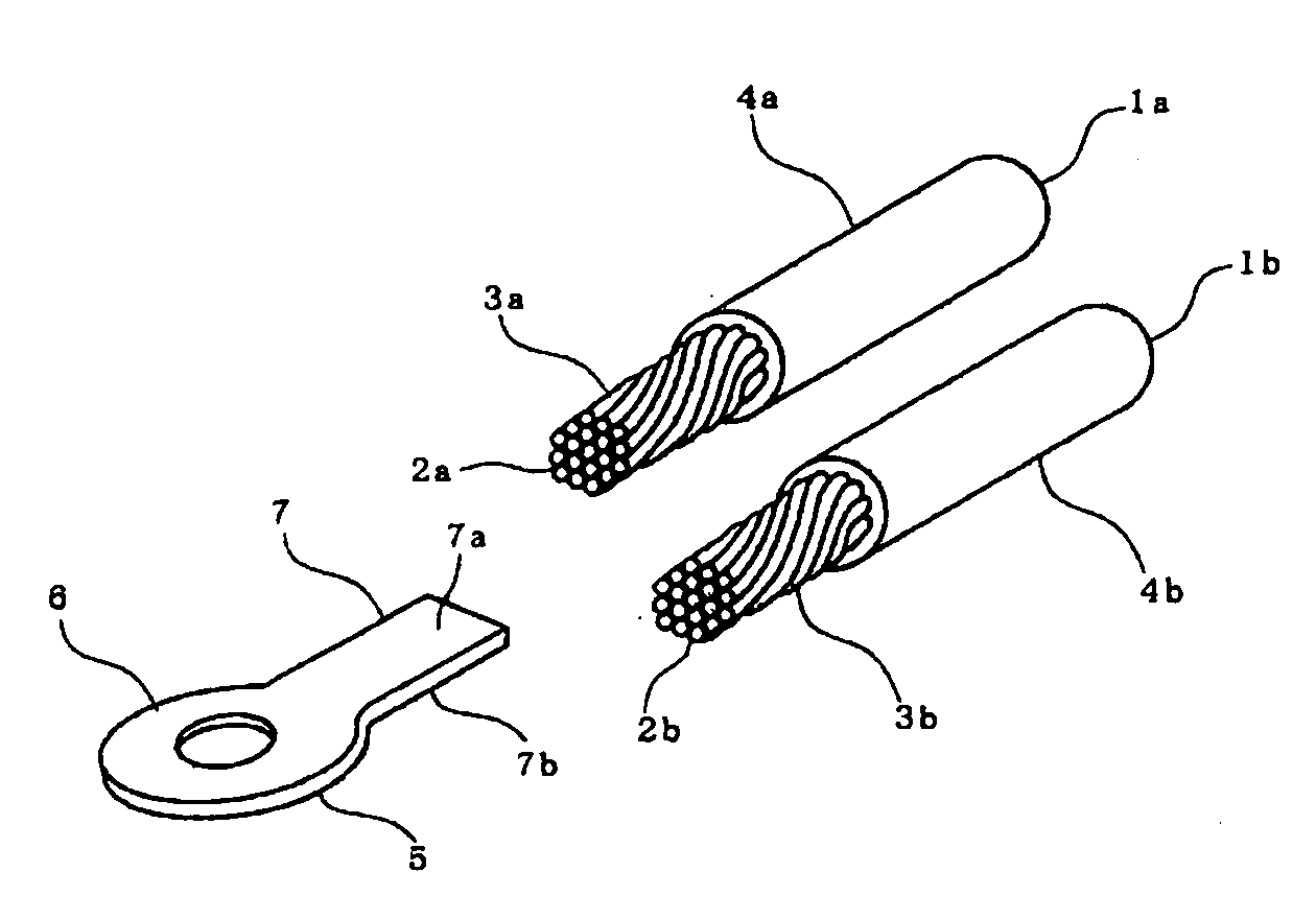
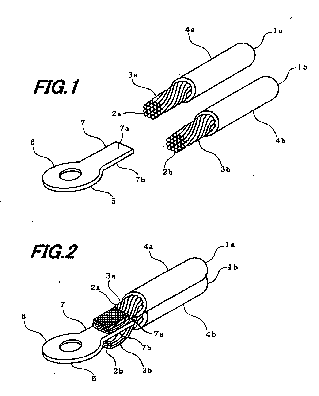
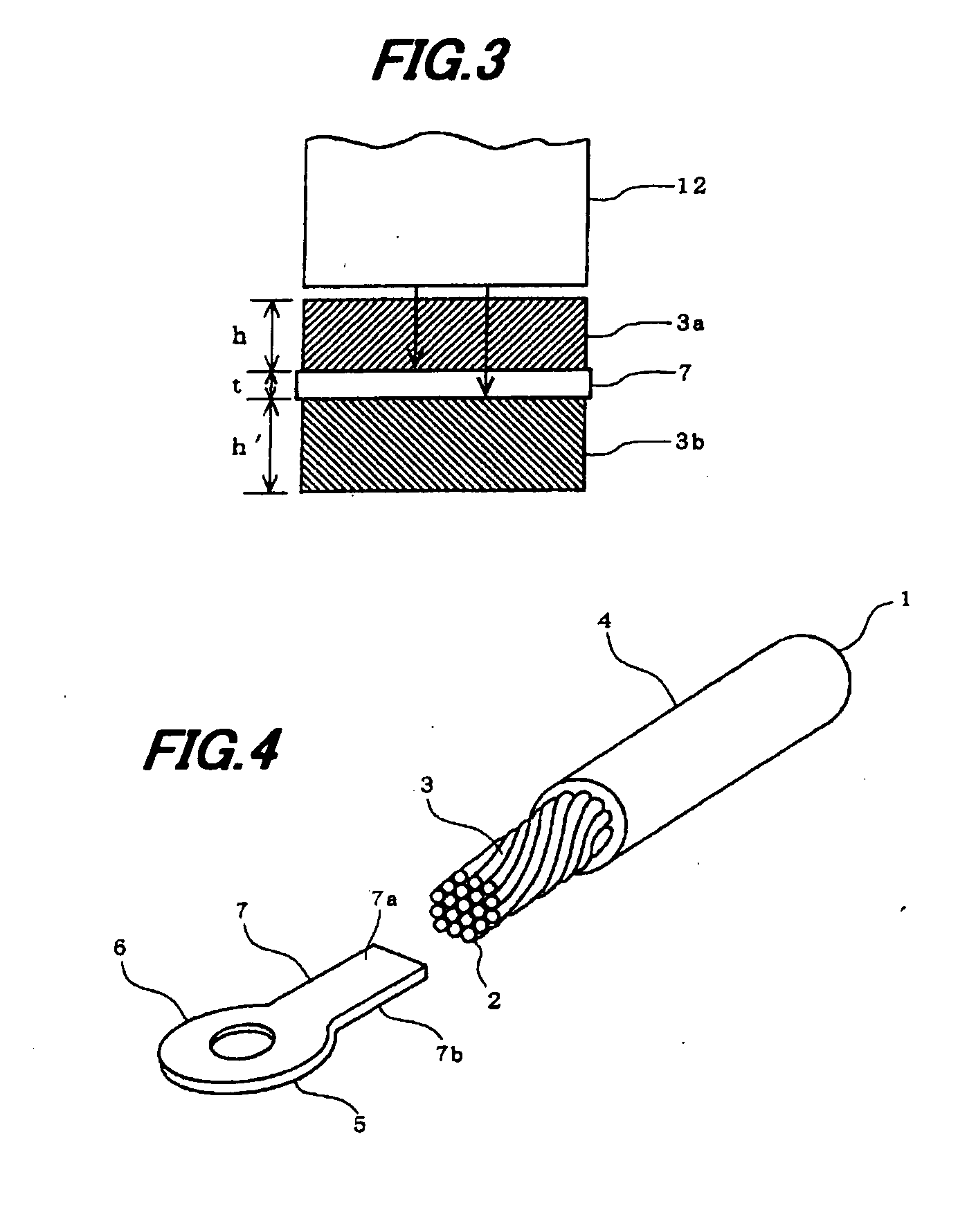
[0069]Using electric wires (1a, 1b) which have Al conductors (3a, 3b) each having a conductor cross-sectional area of 10 mm2 formed by twisting plural Al strands (2a, 2b) with a diameter of 1.0 mm, two of the Al conductors (3a, 3b) in total were positioned in contact with both surfaces of a 1.5 mm thick Cu plate simulating the plate-like terminal 5 shown in FIGS. 1 and 2, and the Cu plate and the Al conductors (3a, 3b) were bonded and integrated at the same time by ultrasonic bonding. In this case, the total conductor cross-sectional area (A) of the two Al conductors (3a, 3b) is 20 mm2, the diameter of the strand (B) is 1.0 mm and an A / B ratio is 20.

example 2

[0070]Using electric wires (1a, 1b) which have Al conductors (3a, 3b) each having a conductor cross-sectional area of 20 mm2 formed by twisting plural Al strands (2a, 2b) with a diameter of 1.0 mm, two of the Al conductors (3a, 3b) in total were positioned in contact with both surfaces of a 1.5 mm thick Cu plate simulating the plate-like terminal 5 shown in FIGS. 1 and 2, and the Cu plate and the Al conductors (3a, 3b) were bonded and integrated at the same time by ultrasonic bonding. In this case, the total conductor cross-sectional area (A) of the two Al conductors (3a, 3b) is 40 mm2, the diameter of the strand (B) is 1.0 mm and an A / B ratio is 40.

example 3

[0071]Using electric wires (1a, 1b) which have Al conductors (3a, 3b) each having a conductor cross-sectional area of 25 mm2 formed by twisting plural Al strands (2a, 2b) with a diameter of 1.0 mm, two of the Al conductors (3a, 3b) in total were positioned in contact with both surfaces of a 1.5 mm thick Cu plate simulating the plate-like terminal 5 shown in FIGS. 1 and 2, and the Cu plate and the Al conductors (3a, 3b) were bonded and integrated at the same time by ultrasonic bonding. In this case, the total conductor cross-sectional area (A) of the two Al conductors (3a, 3b) is 50 mm2, the diameter of the strand (B) is 1.0 mm and an A / B ratio is 50.


PUM

PropertyMeasurementUnit
cross-sectional areaaaaaaaaaaa
total cross-sectional areaaaaaaaaaaa
areaaaaaaaaaaa

Abstract

An electric wire with a terminal including a conductor, and the terminal connected to an end portion of the conductor. The terminal includes a first connecting portion connected to an electrical equipment and a second connecting portion connected to the conductor. The second connecting portion includes a first connection surface and a second connection surface opposite to the first connection surface. The conductor includes a first conductor and a second conductor that are connected to the first connection surface and the second connection surface, respectively, by ultrasonic bonding. A total cross-sectional area of the first conductor and the second conductor is not less than 20 mm2.

Description

[0001]The present application is based on Japanese Patent Application No. 2010-031471 filed on Feb. 16, 2010, the entire contents of which are incorporated herein by reference.BACKGROUND OF THE INVENTION[0002]1. Field of the Invention[0003]The invention relates to an electric wire with terminal and a method of manufacturing the same, in particular, to an electric wire with terminal which is wired inside a device of a vehicle, etc., and has a conductor having a large cross-sectional area, and to a method of manufacturing the same.[0004]2. Description of the Related Art[0005]A wire with terminal in which a terminal for equipment connection is preliminarily bonded to and integrated with a wire conductor is often used for wiring inside a device of a vehicle, etc.[0006]As a method of connecting a terminal to a wire conductor, a method in which a wire conductor having a certain volume (cross-sectional area) is compression-bonded to a surface of a plate-like terminal formed of Cu or a Cu a...

Claims


Application Information

Patent Timeline
Patent Type & Authority Applications(United States)
IPC IPC(8): H01R4/10H01R43/04
CPCH01R4/023Y10T29/49181H01R43/0207H01R4/029
Inventor SAGAWA, HIDEYUKIHORIKOSHI, TOSIYUKIKURODA, HIROMITSUTAKEHARA, HIDEAKISUMI, TORU
Owner HITACHI METALS LTD
Why Eureka
Try Eureka