Clutch transmission mechanism of printing device

Inactive Publication Date: 2011-08-18
PRIMAX ELECTRONICS LTD
View PDF6 Cites 14 Cited by
  • Summary
  • Abstract
  • Description
  • Claims
  • Application Information

AI Technical Summary

Benefits of technology

[0009]It is an object of the present invention to provide a clutch transmission mechanism of a printing device, so that the printing device can be operated in different gear-

Problems solved by technology

The uses of too many motors are not cost-effective.
For example, since the clutch gear set 22 and the motor gear 6 for transmitting the driving force are non-coaxially but radially engaged with e

Method used


Image

  • Clutch transmission mechanism of printing device
  • Clutch transmission mechanism of printing device
  • Clutch transmission mechanism of printing device

Examples


Example

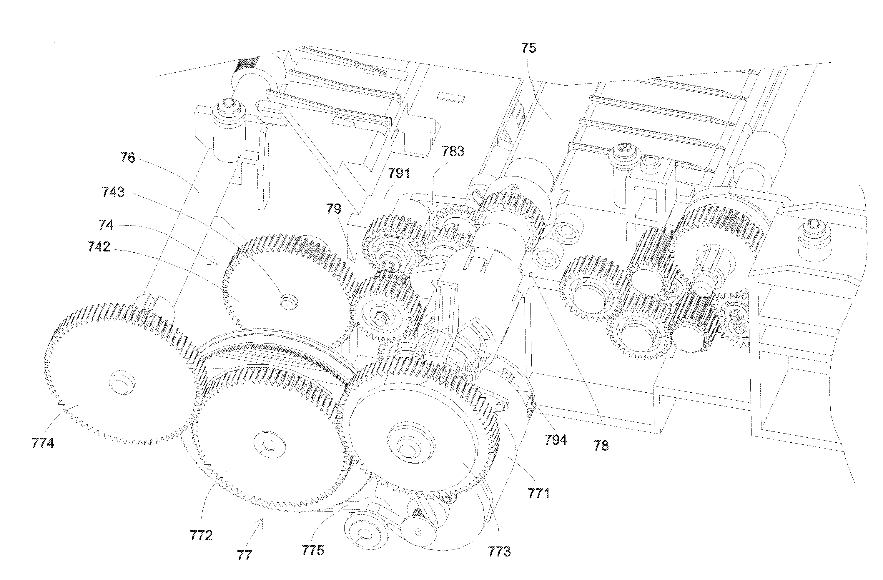
[0035]FIG. 3 is a schematic perspective view illustrating a portion of a printing device according to a first embodiment of the present invention. FIG. 4 is a schematic perspective view illustrating a clutch transmission mechanism and a transmission gear module of a printing device according to a first embodiment of the present invention. As shown in FIGS. 3 and 4, the printing device 7 comprises a sheet input tray 71, a sheet output tray 72, an inkjet printing module 73, a sheet pick-up module 74, a sheet transfer shaft 75, a sheet ejecting shaft 76, a power module 77, a clutch transmission mechanism 78 and a transmission gear module 79. The blank paper is placed on the sheet input tray 71, and then fed into a fixed transmission path to be printed. The printed paper is exited to and placed on the sheet output tray 72. The sheet pick-up module 74 is used for feeding the paper into the transmission path. The paper within the transmission path is transported by the sheet transfer shaf...


PUM


Abstract

A clutch transmission mechanism of a printing device includes a power input shaft, a power input gear, a gear-shifting arm, a first gear-shifting module and a second gear-shifting module. In the cooperation of these components and modules, the printing device can be operated in a first gear-shifting mode or a second first gear-shifting mode. When the printing device can be operated in a first gear-shifting mode or a second first gear-shifting mode, the clutch transmission mechanism coaxially transmits the driving force. As such, the stability of transmitting the driving force is enhanced.

Description

FIELD OF THE INVENTION[0001]The present invention relates to a clutch transmission mechanism, and more particularly to a clutch transmission mechanism of a printing device.BACKGROUND OF THE INVENTION[0002]Printing devices are essential information apparatuses in modern offices. The printing devices include for example copiers, printers, scanners and multifunction peripherals. Among these printing devices, printers are the most popular. Generally, after a printer is connected to a computer, the document file of the computer could be printed on many kinds of media (e.g. blank papers).[0003]FIG. 1 is a schematic perspective view illustrating an inkjet printer according to the prior art. As shown in FIG. 1, the inkjet printer 1 comprises an ink cartridge 10, plural ink nozzles (not shown), a transmission mechanism 11, a sheet input tray 12 and a sheet output tray 13. The ink cartridge 10 is used for storing ink. The ink nozzles are used for ejecting ink. The ink nozzles are disposed at ...

Claims


Application Information

Patent Timeline
IPC IPC(8): F16D21/04
CPCB65H3/0669B65H2403/42B65H2403/722B65H2801/06F16D11/14B65H2220/09
Inventor TU, TUNG-WENZENG, JIANYU, JIAN-GJU
Owner PRIMAX ELECTRONICS LTD
Why Eureka
Try Eureka