Clutch release mechanism and clutch assembly including same

a technology of release mechanism and clutch assembly, which is applied in the direction of friction clutches, interengaging clutches, and clutches, can solve the problems of poor workability, and achieve the effects of reducing the range of movement, reducing the deflection of pressing, and improving the stability of shifting feeling

Active Publication Date: 2011-08-18
HONDA MOTOR CO LTD
View PDF7 Cites 3 Cited by
  • Summary
  • Abstract
  • Description
  • Claims
  • Application Information

AI Technical Summary

Benefits of technology

[0025]According to the clutch release mechanism of the third aspect hereof, in addition to the effects of the invention of the first aspect, the hollow portion of the pressing member pivotally supported by the movable cam plate and the positioning member has the extended hollow portion. The extended hollow portion extends to the turning area of the cylinder projecting portion along the turning direction of the movable cam plate with the positioning member serving as a fulcrum. Therefore, a range can be enlarged where the deflection of the pressing due to the misalignment between the pressing member and the movable cam plate defined in position by the cylindrical boss portion of the fixed cam plate can be prevented substantially. Thus, the shift feeling can be more stabilized. In addition, the permissible range of the misalignment between the fixed cam plate and the pressing member on the movable cam plate side can be more enlarged.
[0026]Acco...

Problems solved by technology

Therefore, there is a ...

Method used


Image

  • Clutch release mechanism and clutch assembly including same
  • Clutch release mechanism and clutch assembly including same
  • Clutch release mechanism and clutch assembly including same

Examples


Embodiment Construction

[0033]It should be understood that only structures considered necessary for clarifying the present invention are described herein. Other conventional structures, and those of ancillary and auxiliary components of the system, will be known and understood by those skilled in the art.

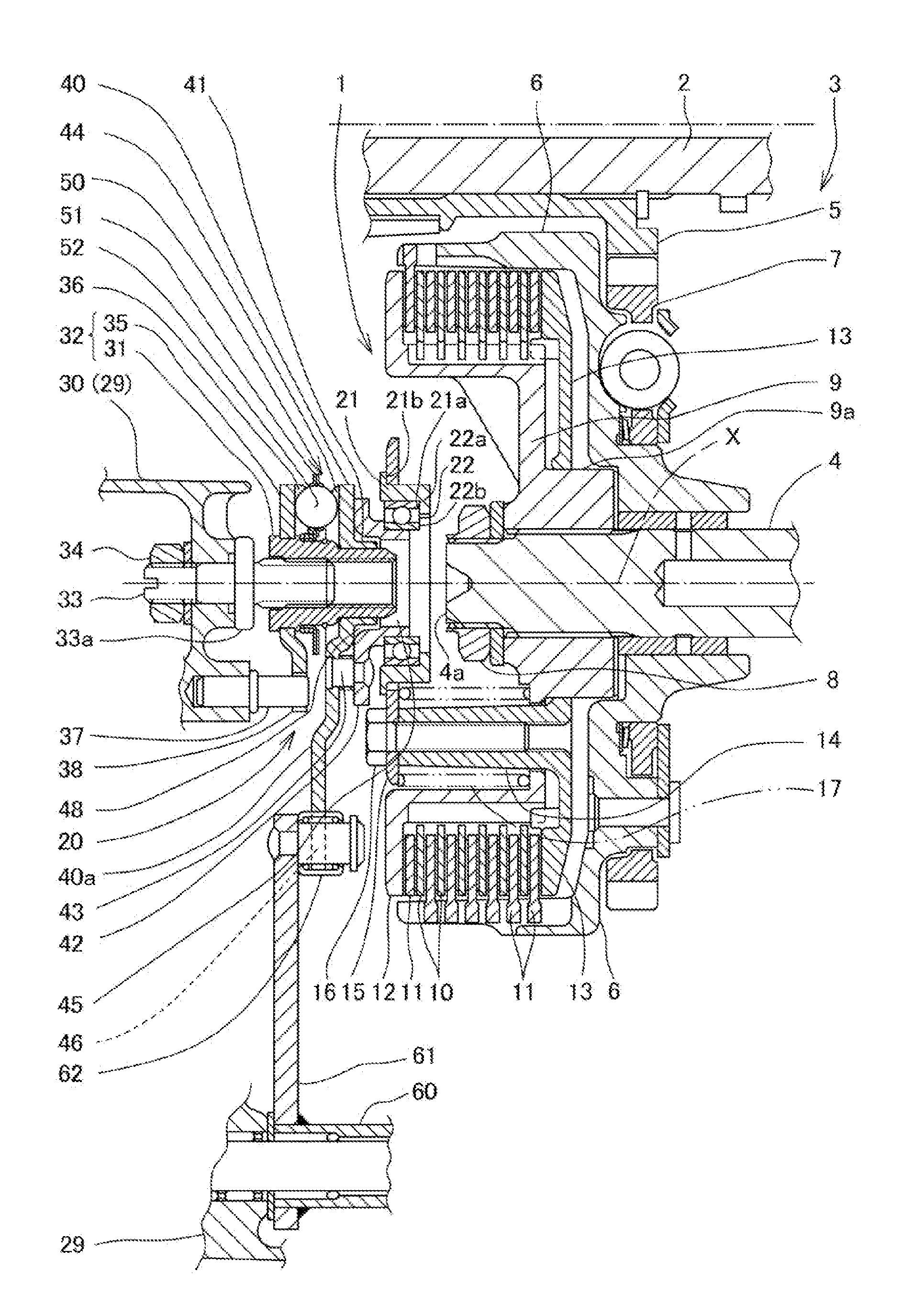
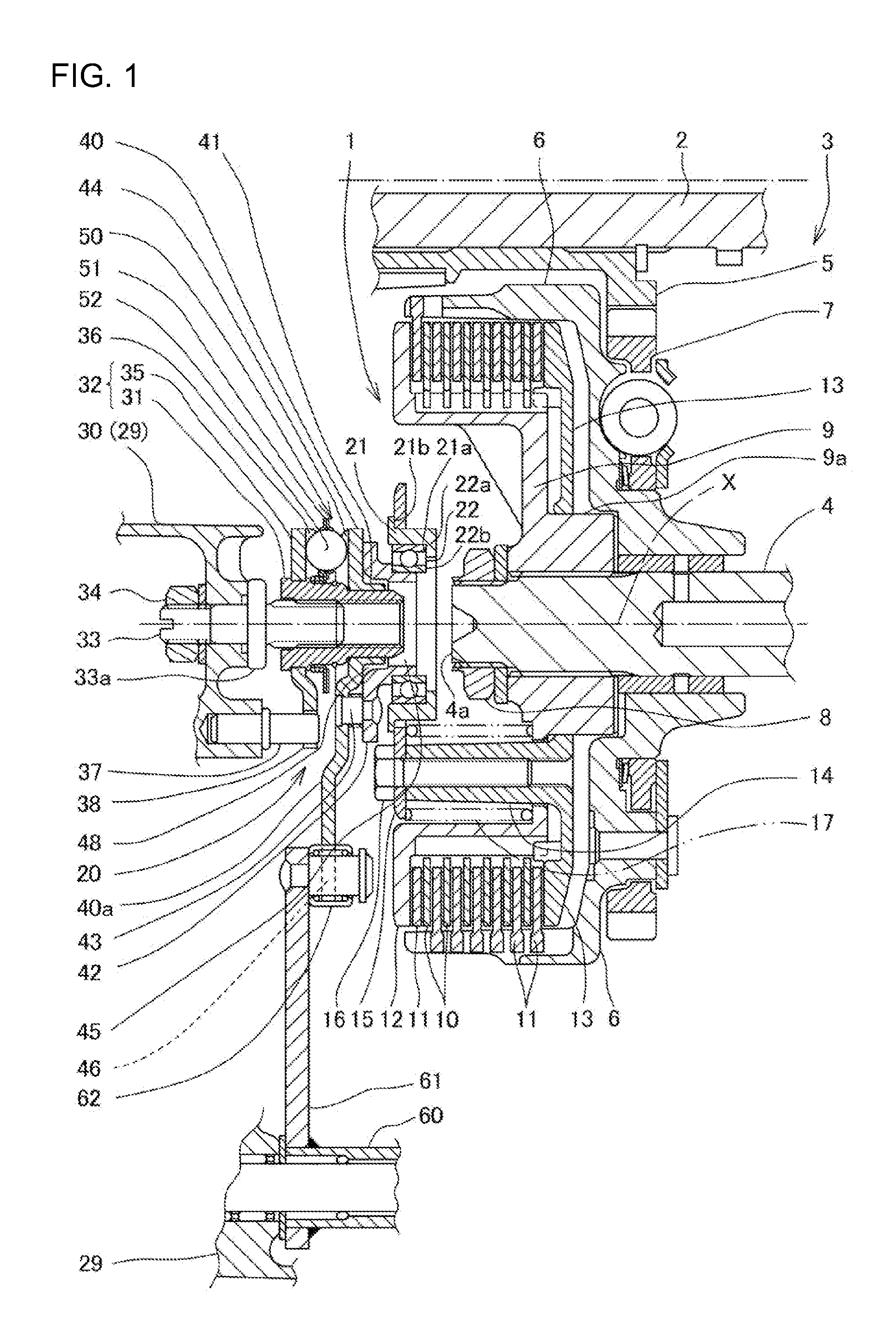
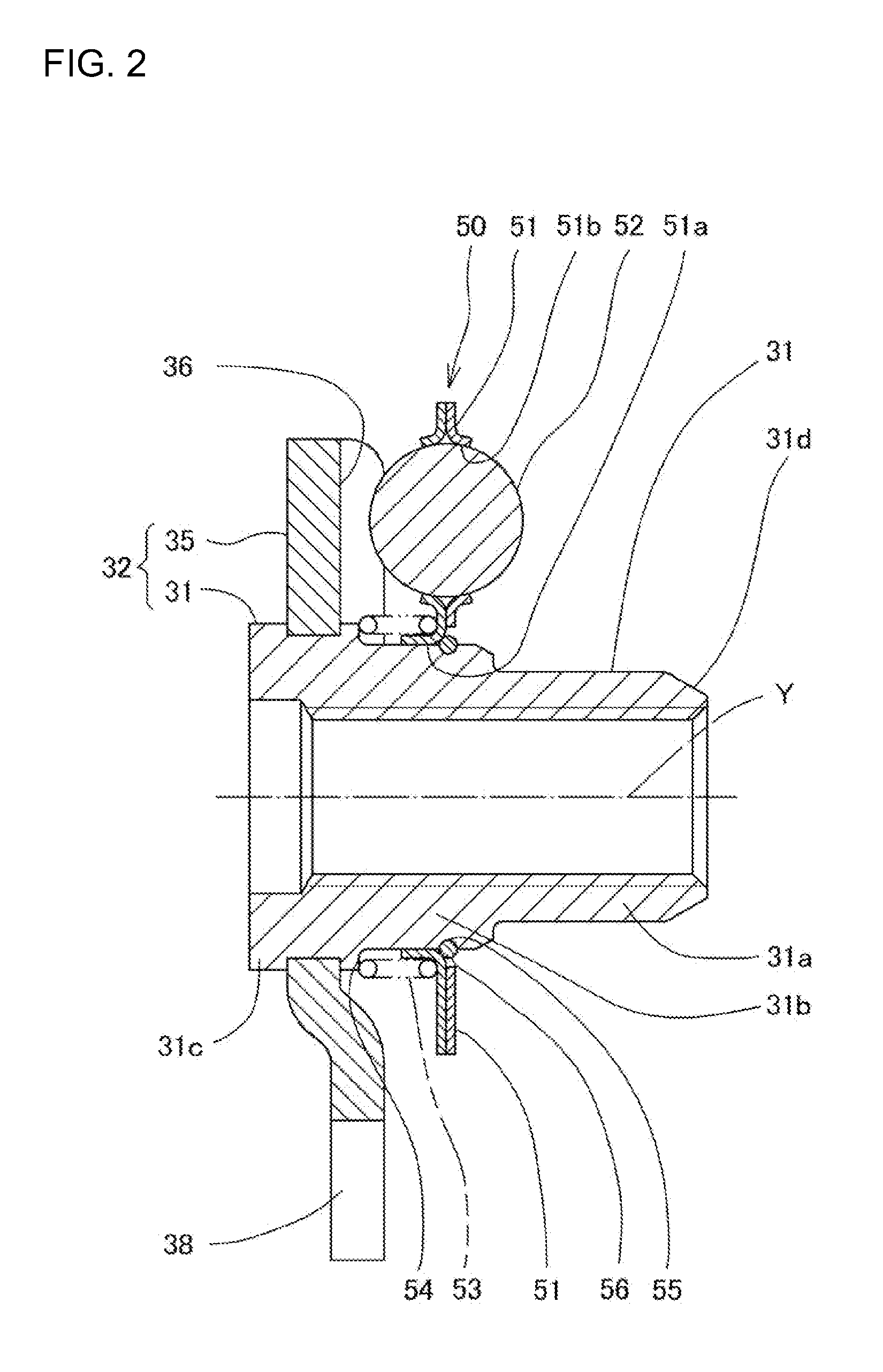
[0034]A clutch release mechanism according to a number of selected illustrative embodiments of the present invention, and a modification resulting from modifying part of the clutch release mechanism, will now be described with reference to FIGS. 1 through 5.

[0035]A clutch release mechanism 20, according to a first illustrative embodiment of the present invention described herein, is used to release the engagement of a multiple disk clutch device installed in a power unit of a motorcycle, an all-terrain vehicle or the like. However, the present invention shall not be limited to the use of a power unit in a vehicle. A clutch mechanism according to an embodiment of the present invention may also be applied to...


PUM


Abstract

A clutch release mechanism includes a fixed cam plate having a cylindrical boss portion, and a movable cam plate supported on the cylindrical boss portion through a cylindrical projecting portion thereof. A ball unit is retained on the cylindrical boss portion by a retainer, and a release member disengages a clutch by transmitting a thrust force, generated by relative turning between the fixed and movable cam plates which hold the ball unit therebetween, to a pressure-applying plate. A pressing member is pressed by the movable cam plate to transmit the thrust force to the release member. The cylindrical projecting portion of the movable cam plate projects toward the pressing member, and is fitted a the hollow portion thereof with a gap therebetween. The movable cam plate presses the pressing member so as to be relatively shiftable on a flat surface perpendicular to a pressing direction.

Description

CROSS-REFERENCE TO RELATED APPLICATIONS[0001]The present invention claims priority under 35 USC 119 based on Japanese patent application No. 2010-028662, filed on Feb. 12, 2010. The entire subject matter of this priority document, including specification claims and drawings thereof, is incorporated by reference herein.BACKGROUND OF THE INVENTION[0002]1. Technical Field[0003]The present invention relates to a clutch release mechanism used to release the engagement of a multiple disk clutch device installed in a power unit, which may be freestanding, or alternatively, which may be incorporated into a vehicle such as a motorcycle, an all-terrain vehicle or the like.[0004]2. Background Art[0005]There is known a clutch release mechanism of a multiple disk clutch device configured as below, as disclosed in e.g. Patent Document 1 mentioned below. A plurality of balls are interposed between a fixed cam plate and a movable cam plate which are opposed to each other. A release member is presse...

Claims


Application Information

Patent Timeline
IPC IPC(8): F16D13/52F16D13/38
CPCF16D13/52F16D2023/123F16D23/12
Inventor KANAI, YUMATSUO, KENJISUZUKI, HIROMI
Owner HONDA MOTOR CO LTD
Why Eureka
Try Eureka