Optical transmission medium shaping method, optical transmission medium shaping apparatus, and optical transmission medium manufacturing method
- Summary
- Abstract
- Description
- Claims
- Application Information
AI Technical Summary
Benefits of technology
Problems solved by technology
Method used
Image

Examples
first embodiment
(1) First Embodiment
Structure
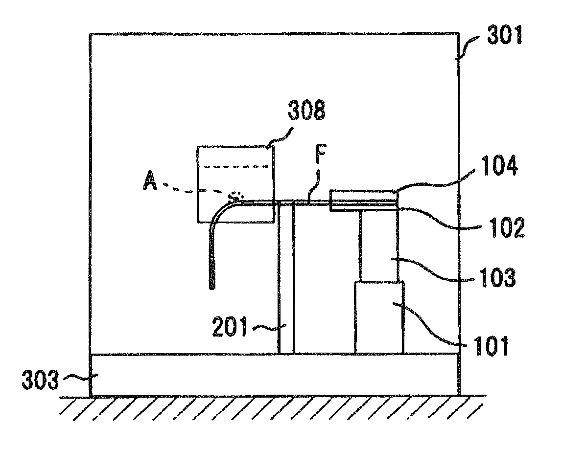
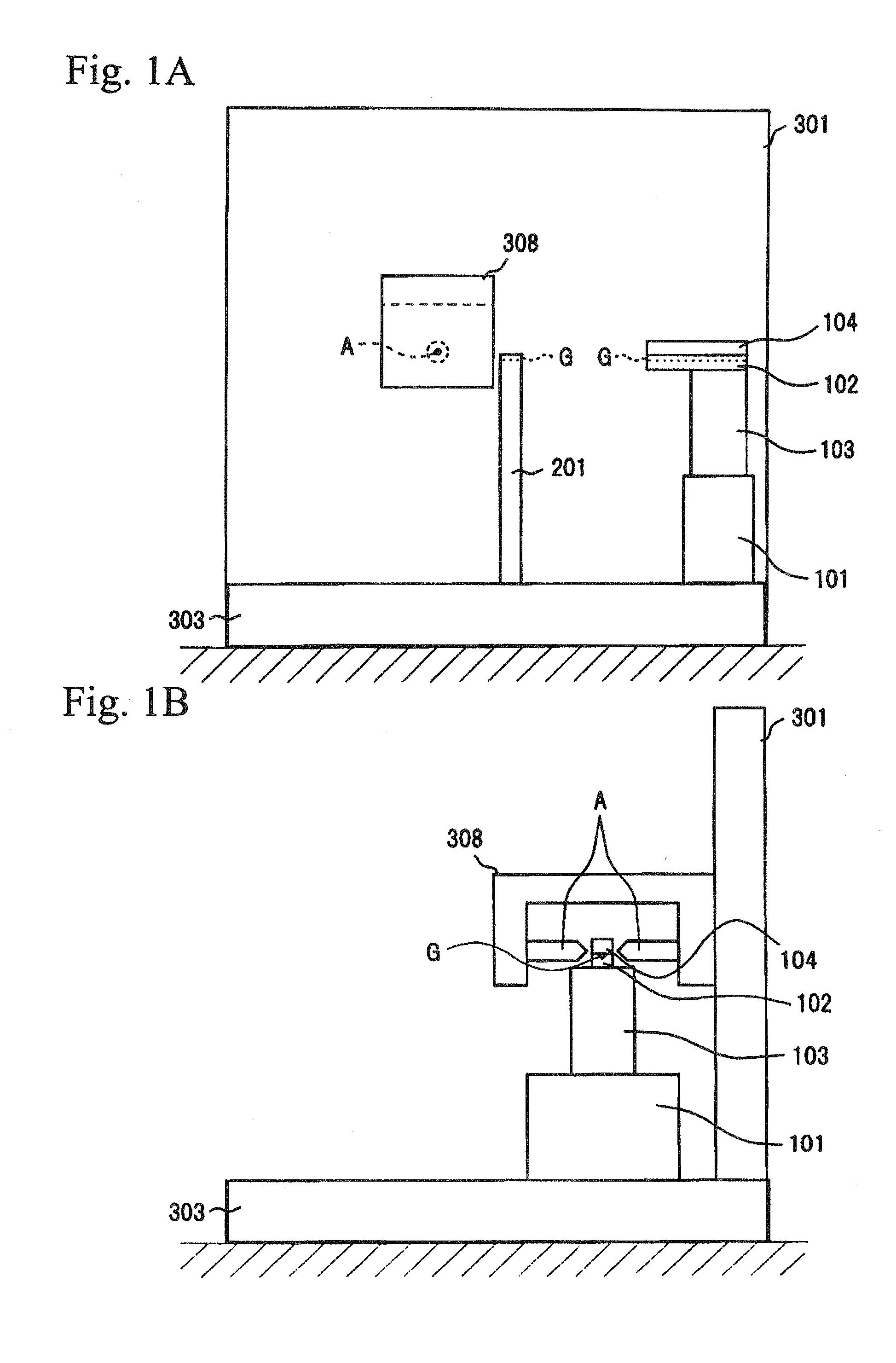
[0023]FIG. 1 includes schematic views showing an optical transmission medium shaping apparatus of the First Embodiment, and FIG. 1A is a front view and FIG. 1B is a right side view.
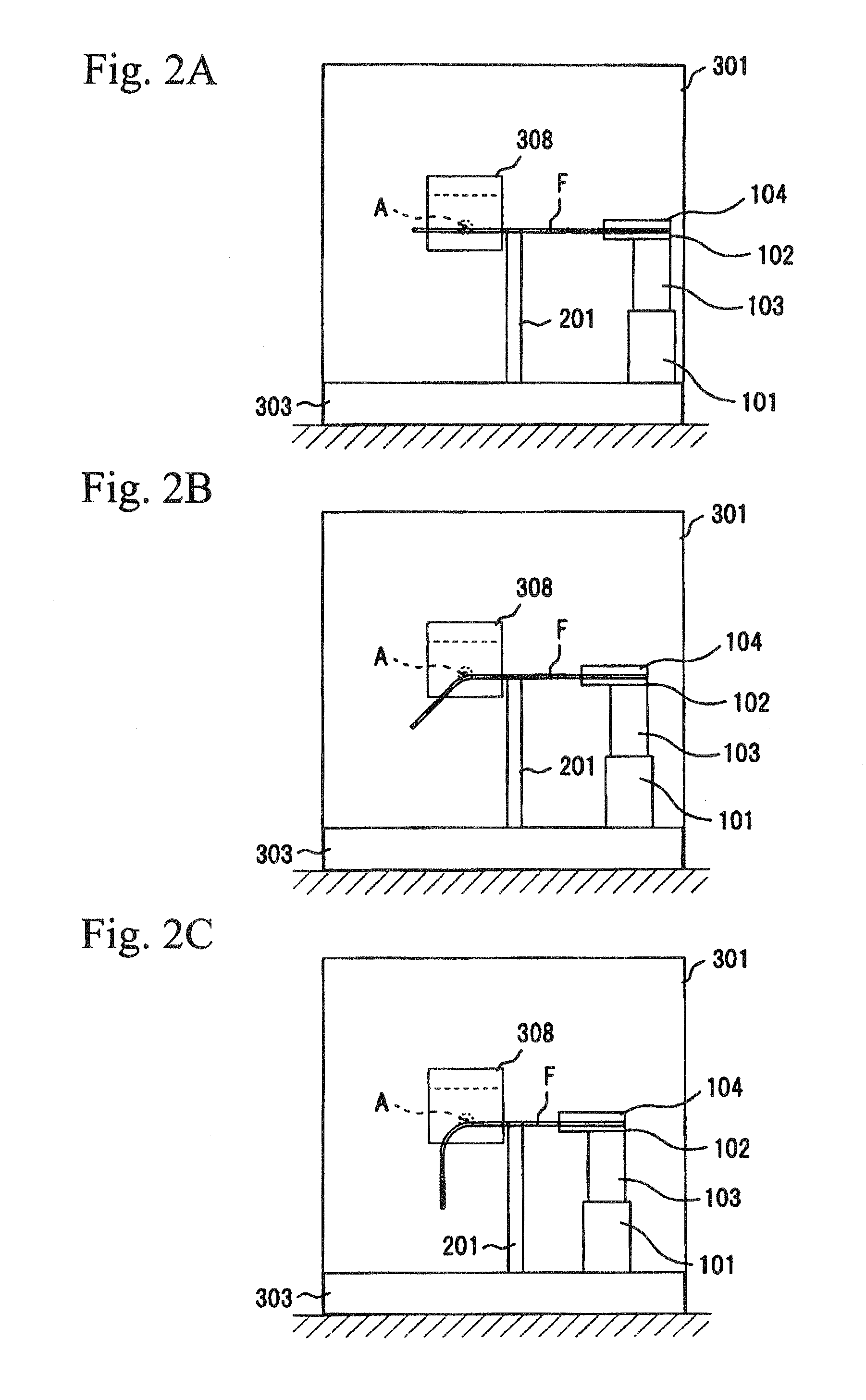
[0024]Reference numeral 101 indicates a horizontal transferring means which is a transferring means, reference numeral 102 indicates an optical fiber carrying mount, reference numeral 103 indicates a supporting column, reference numeral 104 indicates a pressing plate, reference numeral 201 indicates an optical fiber supporting mount, reference numeral 301 indicates a supporting housing, reference numeral 303 indicates a basic pedestal, reference numeral 308 indicates a U-shaped bracket, reference letter A indicates an arc discharge electrode which is a noncontacting heating means, and reference letter G indicates a groove.
[0025]The optical transmission medium shaping apparatus of the First Embodiment has an arc discharge electrode A for heating part of the optical fiber and a ...
second embodiment
(2) Second Embodiment
Structure
[0077]FIG. 3 includes schematic views showing an optical transmission medium shaping apparatus of the Second Embodiment, and FIG. 3A is a front view and FIG. 3B is a right side view.
[0078]Reference numeral 304 indicates a rotation jig, and reference numeral 305 indicates a lever which bends the optical transmission medium.
[0079]In the optical transmission medium shaping apparatus of the Second Embodiment, as shown in FIGS. 3A and 3B, a rotation jig 304 which adjusts angular velocity and is rotatable, is provided on a supporting housing 301 and a lever 305 which bends the optical transmission medium is provided on the rotation jig 304.
[0080]Therefore, curvature radius of the optical transmission medium can be widely adjusted by also adjusting not only transfer rate of the horizontal transferring means 101 but also the angular velocity of the rotation jig 304.
[0081]Other structures are identical to those of First Embodiment, and detailed description is om...
third embodiment
(3) Third Embodiment
Structure
[0096]FIG. 5 includes schematic views showing an optical transmission medium shaping apparatus of Third Embodiment, and FIG. 5A is a front view and FIG. 5B is a right side view.
[0097]Reference numeral 302 indicates a supporting column and reference numeral 306 indicates a transferable pedestal which is a transferring means.
[0098]An optical transmission medium shaping apparatus of the Third Embodiment has an arc discharge electrode A for heating part of an optical fiber and a transferring pedestal 306 for transferring the arc discharge electrode A.
[0099]Then, the arc discharge electrode A and the transferring pedestal 306 are operated together, and the part of the optical fiber is heated while transferring the arc discharge electrode A.
[0100]That is, the arc discharge electrode A, which is not the optical fiber, is transferred.
[0101]Specifically, as shown in FIGS. 5A and 5B, it is preferable that two transferable pedestals 306 be provided on a basic pedes...
PUM
| Property | Measurement | Unit |
|---|---|---|
| Angle | aaaaa | aaaaa |
| Radius | aaaaa | aaaaa |
| Radius | aaaaa | aaaaa |
Abstract
Description
Claims
Application Information
 - R&D Engineer
- R&D Manager
- IP Professional
- Industry Leading Data Capabilities
- Powerful AI technology
- Patent DNA Extraction
Browse by: Latest US Patents, China's latest patents, Technical Efficacy Thesaurus, Application Domain, Technology Topic.
© 2024 PatSnap. All rights reserved.Legal|Privacy policy|Modern Slavery Act Transparency Statement|Sitemap