Recirocating vibration generator

a vibration generator and reciprocating technology, applied in the direction of mechanical vibration separation, dynamo-electric machines, supports/enclosements/casings, etc., can solve the problems of increasing power consumption and large size, and achieve the effect of reducing power consumption, improving vibration strength, and reducing the time for attenuation of vibration

Inactive Publication Date: 2011-08-18
SANYO SEIMITSU
View PDF42 Cites 39 Cited by
  • Summary
  • Abstract
  • Description
  • Claims
  • Application Information

AI Technical Summary

Benefits of technology

[0017]Summarizing the advantageous effects of the present invention, the present invention makes the magnetization direction of the toroidal coil and the magnetized direction of the ring-shaped permanent magnet substantially parallel and makes the inside ends of the first toroidal coil and the oppositely wound series second toroidal coil the same magnetic pole, so the magnetic circuit becomes a closed loop. This contributes to improvement of the vibration strength or reduction of the power consumption. Further, it enables reduction of the time for attenuation of vibration.
of the present invention, the present invention makes the magnetization direction of the toroidal coil and the magnetized direction of the ring-shaped permanent magnet substantially parallel and makes the inside ends of the first toroidal coil and the oppositely wound series second toroidal coil the same magnetic pole, so the magnetic circuit becomes a closed loop. This contributes to improvement of the vibration strength or reduction of the power consumption. Further, it enables reduction of the time for attenuation of vibration.

Problems solved by technology

Obtaining the required vibration force leads to a larger size due to the increased number of turns of the coil 52 or an increase in the power consumption due to the increase in the alternating current.

Method used


Image

  • Recirocating vibration generator
  • Recirocating vibration generator
  • Recirocating vibration generator

Examples


Embodiment Construction

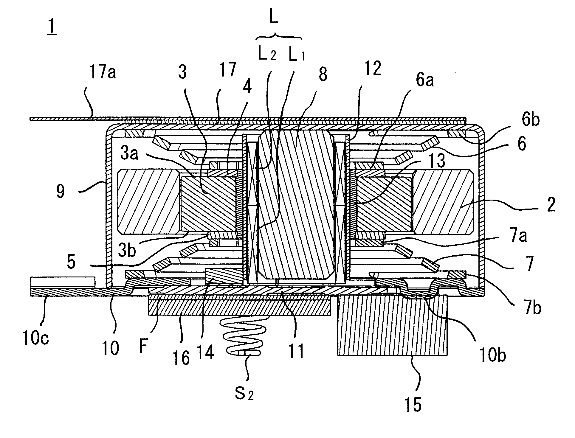
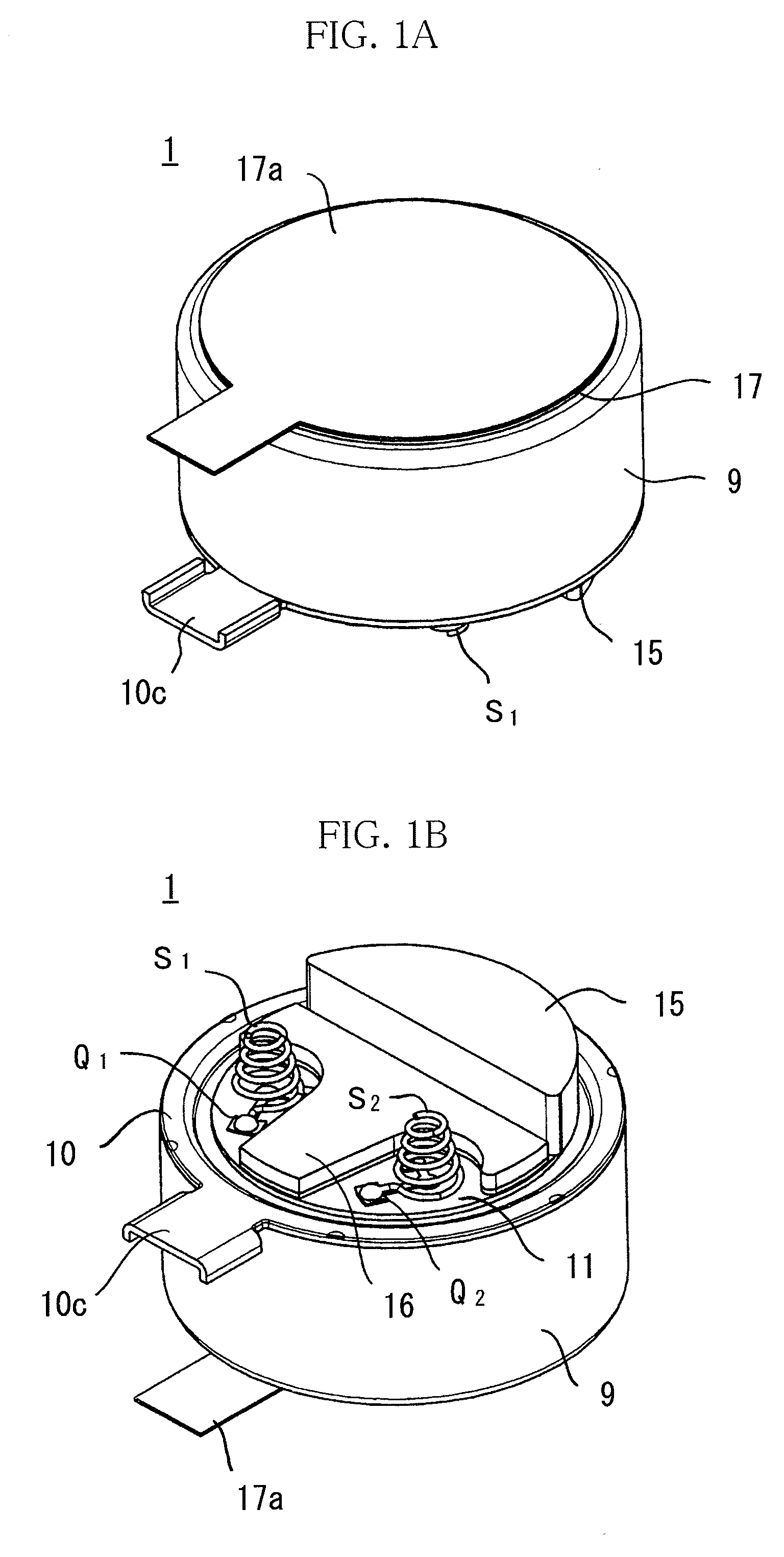
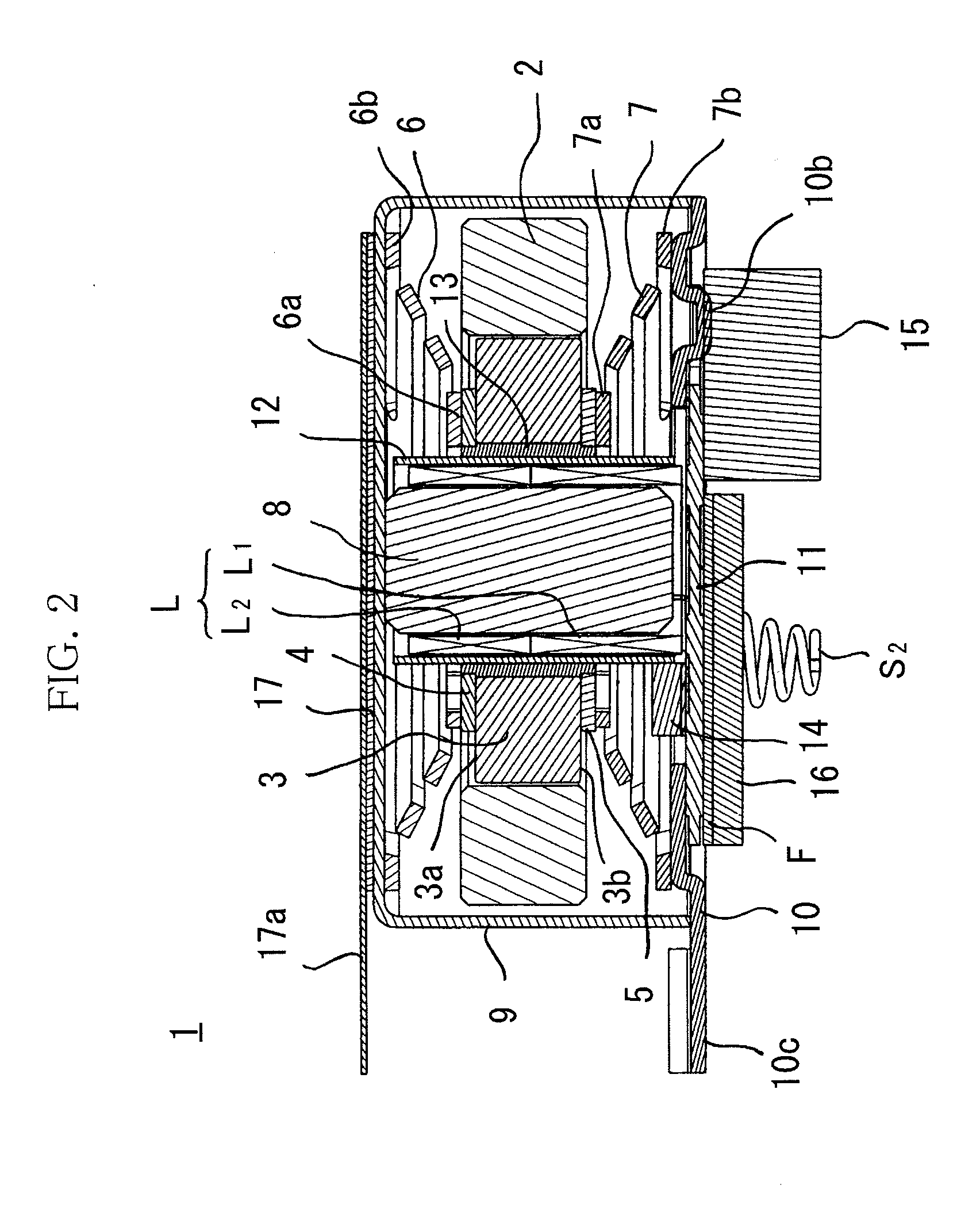
[0027]Next, an embodiment of the present invention will be explained based on the attached drawings. A vibration linear actuator 1 of the present embodiment is provided with a ring-shaped weight 2, a ring-shaped permanent magnet 3 fit in a center hole H of the weight 2 and magnetized by a single pole in a thickness direction between a first end face 3a and a second end face 3b, a ring-shaped first pole piece plate 4 adhered to the first end face 3a by an adhesive, a ring-shaped second pole piece plate 5 adhered to the second end face 3b by an adhesive, a first plate spring 6 having an inner circumference side hanging part 6a fastened to the first pole piece plate 4 by for example spot welding, adhesion, or another means and having an outer circumference side hanging part 6b fastened to a bottom surface of a recessed case 9, a second plate spring 7 having an inner circumference side hanging part 7a fastened to the second pole piece plate 5 and having an outer circumference side hangi...


PUM


Abstract

A reciprocating vibration generator making the magnetic circuit of a permanent magnet a closed loop so as to obtain a high vibration force, specifically a vibration linear actuator having a ring-shaped weight, a reciprocating vibrator having a ring-shaped permanent magnet in a center hole of the weight, a first plate spring and a second plate spring supporting this reciprocating vibrator with respect to a recessed case and an end plate to be able to elastically displace in a thickness direction between a first end face and a second end face, a tube-shaped toroidal coil running through a center hole of the ring-shaped permanent magnet and generating a reciprocating vibration magnetic field for driving the ring-shaped permanent magnet to reciprocate in the thickness direction, and a columnar core running through the inside of this toroidal coil, wherein the ring-shaped permanent magnet is magnetized in the thickness direction, and the toroidal coil has a lower stage toroidal coil and an upper stage toroidal coil coaxial with and adjacent to the same, wound in the opposite direction, and connected in series with the same.

Description

CROSS-REFERENCE TO RELATED APPLICATION[0001]This application is based upon and claims the benefit of priority of the prior Japanese Patent Application No. 2010, 031207, filed on Feb. 16, 2010, the entire contents of which are incorporated herein by reference.BACKGROUND OF THE INVENTION[0002]1. Field of the Invention[0003]The present invention relates to a reciprocating vibration generator which is to be built into a mobile phone etc., more particularly relates to a structure of a reciprocating vibration generator having a weight engaging in reciprocating linear motion.[0004]2. Description of the Related Art[0005]As shown in FIG. 8, a vibration linear actuator 51 disclosed in Japanese Patent Publication (A) No. 2003-154314 is provided with a ring-shaped external yoke 54 as a weight having a ring-shaped permanent magnet 55 at its inner circumference side, a first plate spring 57 fastened to a first end face 54a of this external yoke 54 by elastically deforming an outer circumference s...

Claims


Application Information

Patent Timeline
Patent Type & Authority Applications(United States)
IPC IPC(8): H02K33/00
CPCB06B1/045H02K33/16H02K5/225
Inventor KEISUKE, FURUICHTAKAHIRO, TAKAGI
Owner SANYO SEIMITSU
Why Eureka
Try Eureka