
Method of determining an overlap distance of an optical head and digital exposure device using the method

a technology of overlap distance and digital exposure device, which is applied in the direction of measurement devices, instruments, photomechanical treatment, etc., can solve the problems of reproducing masks, increasing the manufacturing cost of display substrates, and relatively high mask reproduction costs

Active Publication Date: 2011-08-18
SAMSUNG DISPLAY CO LTD
View PDF11 Cites 12 Cited by
  • Summary
  • Abstract
  • Description
  • Claims
  • Application Information

AI Technical Summary

Benefits of technology

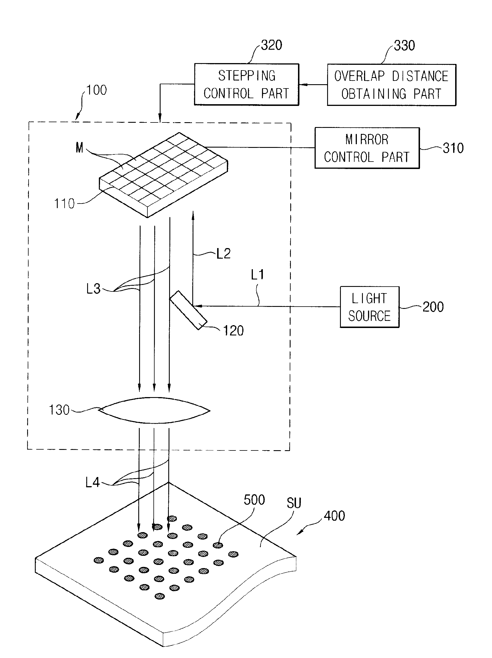
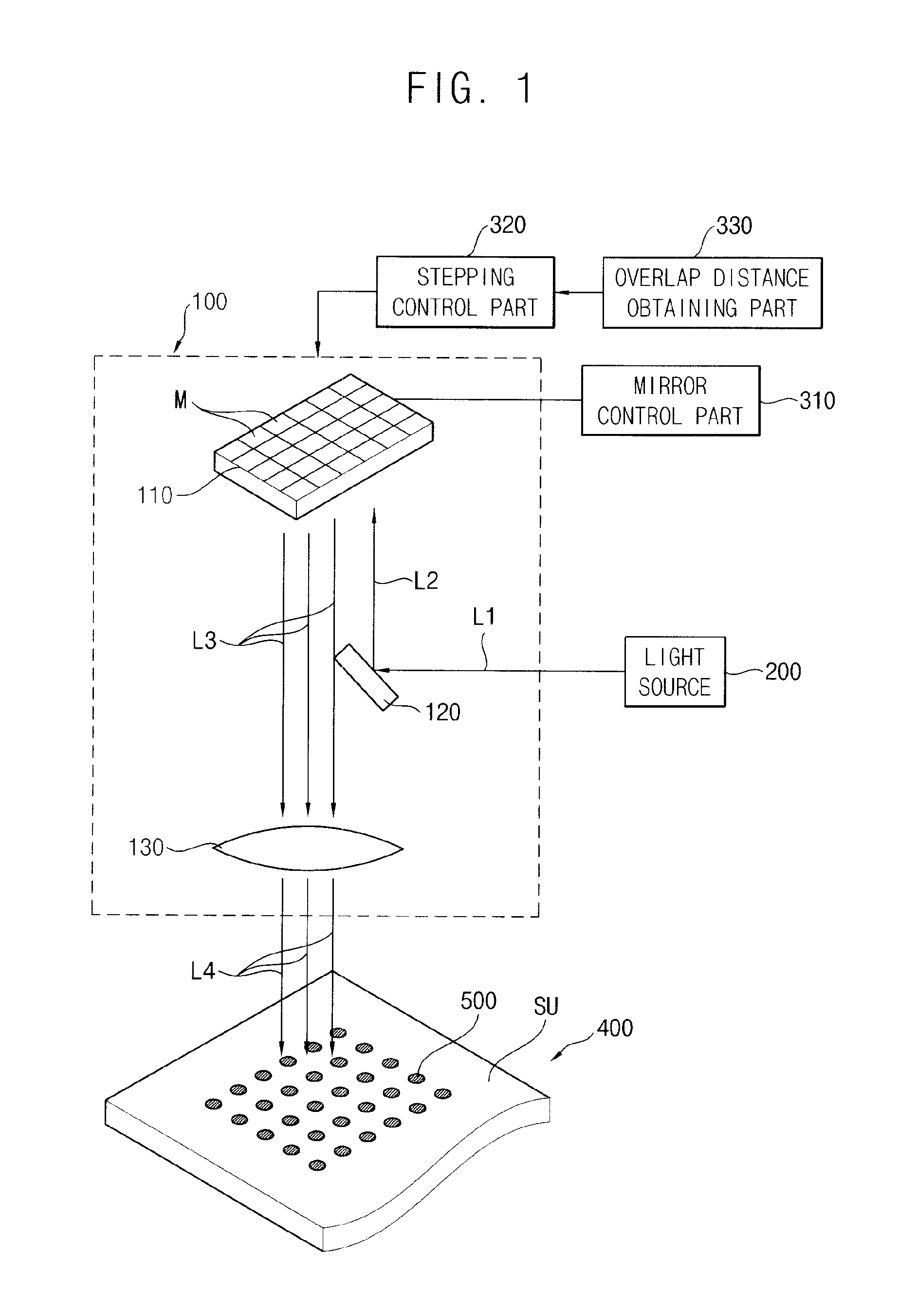
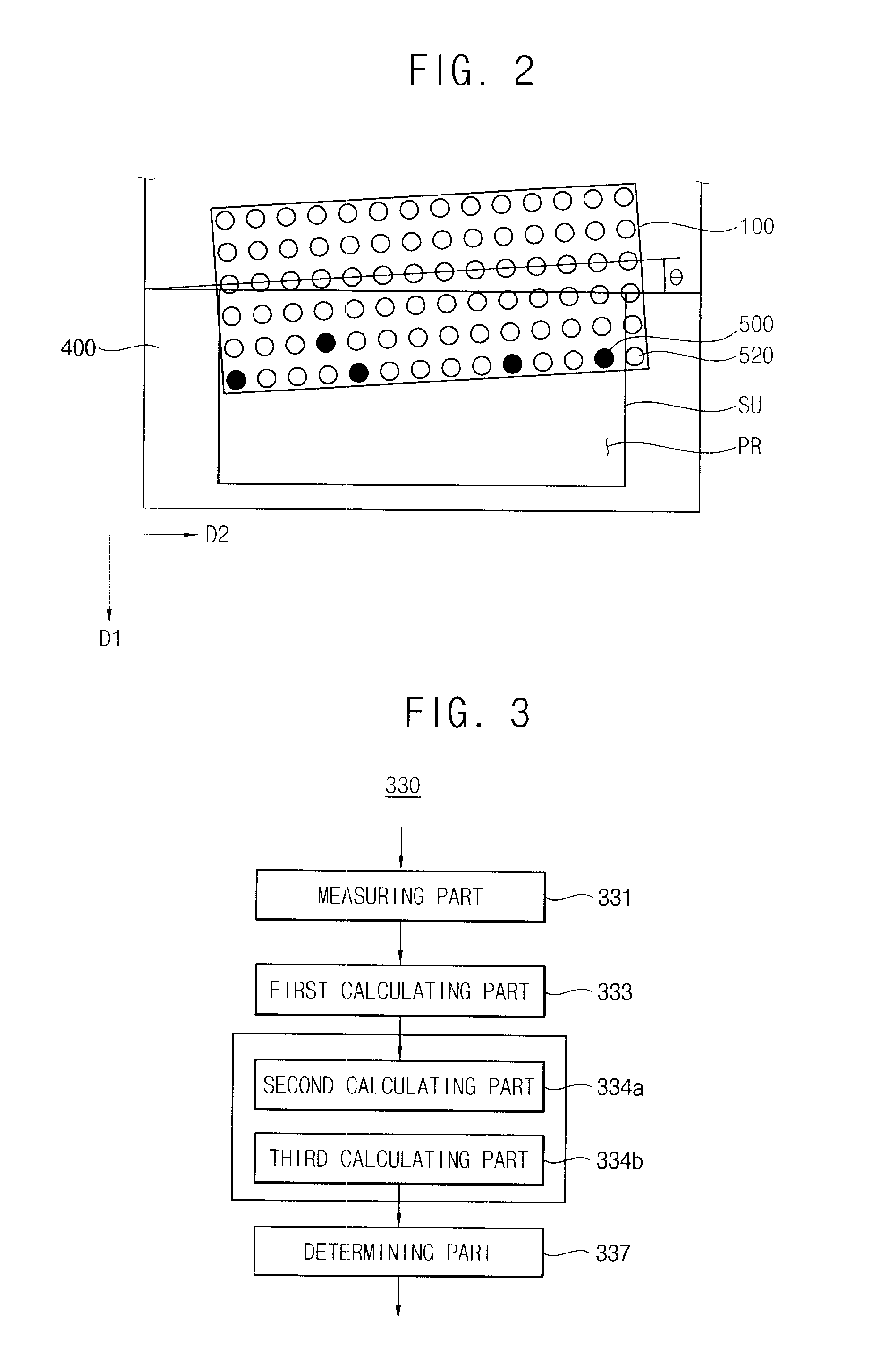
[0013]Exemplary embodiments of the present invention disclose an apparatus. The apparatus includes a compensation part configured to detect an overlap area in a direct patterning using an optical lithography to compensate errors associated with the overlap area. The overlap area is determined by measuring positions and light amount of each light spot distributed on a substrate and the distribution is calculated by applying a Gaussian distribution to the measured positions and light amount distribution. The substrate comprises a first area comprising a plurality of sectors and a second area comprising a plurality of sectors, and a first accumulated amount is measured corresponding to the respective sectors of the first area in response to detection of a optical head scanning in a first direction and a second accumulated amount is measured corresponding to the respective sectors of the second area overlapped with the sectors of the first area in response to detection of a optical head is second scanned in the first direction after being moved in a second direction by a first distance. A control part is configured to control of a mirror arranged in matrix, the control being associated with selectively activating and inactivating light incidence on the substrate. The mirror is controlled by the overlap area and the overlap area is determined according to a uniformity of the summation of the first accumulated light amount and the second accumulated light amount.

Problems solved by technology

Since a reproduction cost of the mask is relatively high, reproducing the mask may increase the manufacturing cost of a display substrate.
However, when the substrate is scanned by the exposure device, an overlapped area may be generated.
In this approach, the overlapped area of the substrate can be exposed by the exposure device at least more than two times so that unnecessary exposures in terms of generating patterns can not only be a burden to manufacturing a display substrate but adversely affect a manufacturing yield since a uniformity of the photoresist pattern may be decreased.

Method used


Image

  • Method of determining an overlap distance of an optical head and digital exposure device using the method
  • Method of determining an overlap distance of an optical head and digital exposure device using the method
  • Method of determining an overlap distance of an optical head and digital exposure device using the method

Examples


Embodiment Construction

[0027]Advantages and features of the present invention can be understood more readily by reference to the following detailed description of exemplary embodiments and the accompanying drawings. The present invention may, however, be embodied in many different forms and should not be construed as limited to the example embodiments set forth herein. Rather, these example embodiments are provided so that this disclosure will be thorough and complete, and will fully convey the scope of the present invention to those skilled in the art. In the drawings, the sizes and relative sizes of layers and regions may be exaggerated for clarity.

[0028]It is understood that when an element or layer is referred to as being “on,”“connected to” or “coupled to” another element or layer, it can be directly on, connected or coupled to the other element or layer or intervening elements or layers may be present. In contrast, when an element is referred to as being “directly on,”“directly connected to” or “dir...


PUM


Abstract

An apparatus and a method for determining an overlap distance of an optical head is disclosed. Positions and light amount distributions of each light spot can be measured, which may be provided from an optical head to a substrate. Gaussian distribution may be applied to the positions and the light amount distributions to calculate a compensation model of each of the light spots. A first accumulated light amount corresponding to each first area of the substrate may be calculated if the optical head is scanning along a first direction of the substrate using the compensation model. A second accumulated light amount corresponding to each second area overlapped with the each first area is calculated if the optical head is scanning along the first direction, which is moved in a second direction by a first distance using the compensation model. An overlap distance may be determined based on a uniformity of summations of the first and second accumulated light amount.

Description

CROSS-REFERENCE TO RELATED APPLICATION[0001]This application claims priority to and benefit of Korean Patent Application No. 2010-14430, filed on Feb. 18, 2010, which is herein incorporated by reference for all purposes as if fully set forth herein.BACKGROUND OF THE INVENTION[0002]1. Field of the Invention[0003]Exemplary embodiments of the present invention relate to an apparatus and a method for determining an overlap distance of an optical head. More particularly, exemplary embodiments of the present invention relate to a digital exposure device and a method for determining an overlap distance of an optical head used for a digital exposure.[0004]2. Description of the Related Art[0005]Generally, in order to form a metal pattern of a thin-film transistor (“TFT”) by using a metal layer and a photoresist layer which may be sequentially formed in a substrate, the metal pattern may be formed using a mask having a design of a metal pattern which may be disposed on the photoresist layer. ...

Claims


Application Information

Patent Timeline
Patent Type & Authority Applications(United States)
IPC IPC(8): G01B11/14
CPCG01B11/14G03F7/70475G03F7/70291G03F7/70075G03F7/70191G03F7/70308G03F7/7055G03F7/70883
Inventor YUN, SANG-HYUNLEE, HI-KUKBAE, SANG-WOOKIM, CHA-DONGPARK, JUNG-IN
Owner SAMSUNG DISPLAY CO LTD
Learn More