Ratiometric analog-to-digital conversion circuit

Active Publication Date: 2022-02-24
SILICON WORKS CO LTD
View PDF13 Cites 0 Cited by
  • Summary
  • Abstract
  • Description
  • Claims
  • Application Information

AI Technical Summary

Benefits of technology

The present patent provides a ratiometric analog-to-digital conversion circuit that can operate at high speeds and reduce design area. It also improves the accuracy of ratiometric conversion by compensating for conversion errors caused by low reference voltage. This circuit achieves this by monitoring information that has a proportional value with the power supply voltage ranges. Overall, the circuit improves the accuracy of input and output proportional conversion through the compensation of conversion errors.

Problems solved by technology

However, since the SAR ADC needs to include the level shifter as described above, the SAR ADC requires a large area in design, which acts as a cause of increasing a chip area.
Further, since the SAR ADC is required to transfer a signal between the different voltage ranges through the level shifter, the SAR ADC has a limitation in implementing a high-speed operation.

Method used


Image

  • Ratiometric analog-to-digital conversion circuit
  • Ratiometric analog-to-digital conversion circuit

Examples


Embodiment Construction

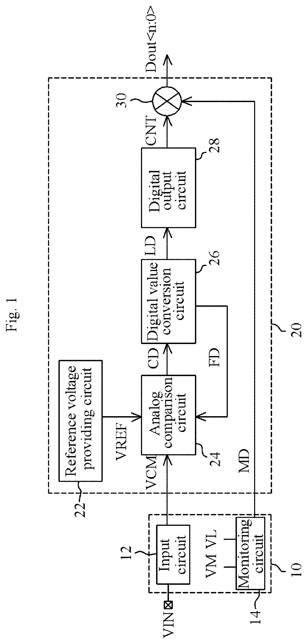
[0026]The present disclosure discloses a ratiometric analog-to-digital conversion circuit.

[0027]The ratiometric analog-to-digital conversion circuit of the present disclosure is to receive an input signal as an analog signal and output a digital signal generated by analog-to-digital converting the input signal. The digital signal is outputted to have a value proportional to the input signal.

[0028]The ratiometric analog-to-digital conversion circuit of the present disclosure may be designed inside a micro control unit (not illustrated) which is fabricated as a chip, or may be designed to be fabricated as a separate chip.

[0029]The ratiometric analog-to-digital conversion circuit of the present disclosure may be configured to receive an input signal through a signal input terminal of a chip, and provide a digital signal, generated by an analog-to-digital conversion, to an internal component thereof or to an external component through a signal output terminal.

[0030]The ratiometric analo...


PUM


Abstract

A ratiometric analog-to-digital conversion circuit includes a first voltage range operation circuit configured to use a first power supply voltage of a first voltage range, and output an analog signal corresponding to an external input signal; and a second voltage range operation circuit configured to use a second power supply voltage of a second voltage range, generate a digital value by analog-to-digital converting the analog signal, feed back the digital value for analog-to-digital conversion, and output a digital signal corresponding to the digital value and proportional to the input signal.

Description

BACKGROUND1. Technical Field[0001]Various embodiments generally relate to an analog-to-digital conversion circuit, and more particularly, to a ratiometric analog-to-digital conversion circuit which outputs a digital signal of a second voltage range in response to an analog signal as an input signal of a first voltage range.2. Related Art[0002]In general, a home appliance is configured to perform electronic control so as to provide various functions, and may include a micro control unit for the electronic control.[0003]The micro control unit is configured to electrically interface with various external components and perform necessary control. For example, the micro control unit may be configured to receive an analog input signal from an external signal source such as a sensor, generate a digital signal for the input signal, and implement necessary control using the digital signal.[0004]The micro control unit may be designed to include an analog-to-digital converter (hereinafter, ref...

Claims


Application Information

Patent Timeline
IPC IPC(8): H03M1/06H03M1/46
CPCH03M1/0619H03M1/468H03M1/462H03M1/38H03M1/403H03M1/1014
Inventor YOON, JANG HYUN
Owner SILICON WORKS CO LTD
Why Eureka
Try Eureka