Method for estimating road surface state

a road surface and state estimation technology, applied in the field of road surface state estimation, can solve the problems of inability to distinguish between smooth asphalt road surface and slightly wet road surface, and the extremely limited number of determinable road surface states, so as to achieve accurate estimation, precise state, and accurate estimation

Active Publication Date: 2011-08-18
BRIDGESTONE CORP
View PDF2 Cites 29 Cited by
  • Summary
  • Abstract
  • Description
  • Claims
  • Application Information

AI Technical Summary

Benefits of technology

[0024]According to the aspect <6>, when the measured wave profile satisfies at least one of the third and forth determination conditions, the road surface corresponding to the measured wave profile is estimated at in a dry state, so that the dry state can be accurately estimated.
[0025]According to the aspect <7>, when the measured wave profile satisfies none of the first to forth determination conditions, it is determined not to be any of wet, frozen and dry states, which corresponds to a slushy or snowy state, so that the slushy and snowy state can be accurately estimated.
[0026]According to the aspect <8>, the first to third steps are carried out in this order as mentioned above, so that even when the measured wave profile satisfies two or more of the first to forth requirements, a more precise state can be estimated alternatively. This can further enhance the accuracy of the estimation.

Problems solved by technology

As a result, it is found that, for example, a smooth asphalt road surface and slightly wet road surface cannot be distinguished.
It is a problem that the number of determinable road surface state is extremely limited.

Method used


Image

  • Method for estimating road surface state
  • Method for estimating road surface state
  • Method for estimating road surface state

Examples


examples

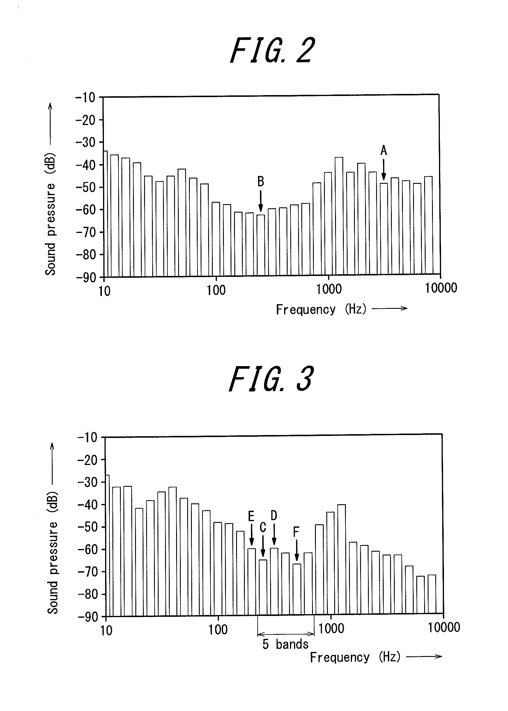
[0054]A vehicle was actually driven to examine relevance of an estimated state of a road surface based on a sound detection signal from a ground contact surface sound detection unit during the driving with respect to an actual condition of a road surface on which the vehicle was driven. The road surface states to be distinguished were categorized as dry, wet, frozen and slushy / snowy states, and the estimations were done according to the above-mentioned method.

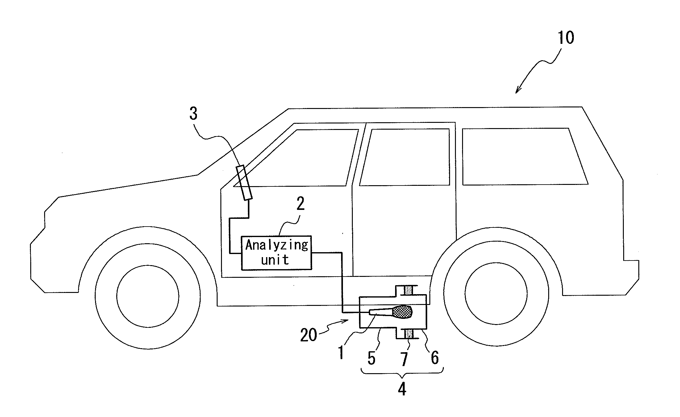
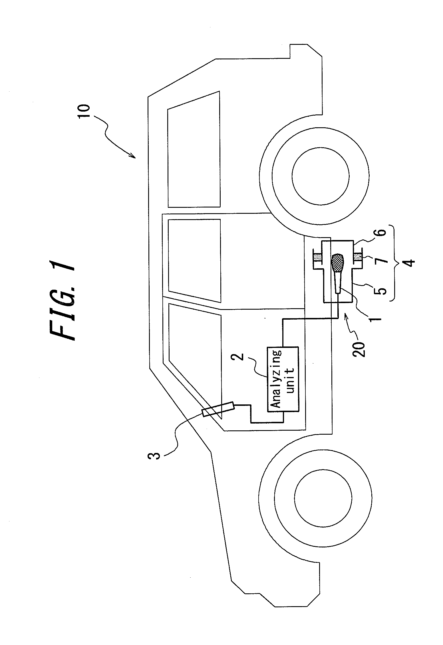
[0055]A four-wheel-drive vehicle was used as a test vehicle. A microphone was housed in a container and the container was mounted so as to be able to collect sounds from anterior of the rear wheel of the vehicle. The vehicle was traveled along general roads in Hokkaido and Tohoku areas in Japan at 30-70 km / h. The sounds were collected during the travel. Table 1 shows the results of the determination, where the rates are indicated in percent.

TABLE 1RoadResult of determination from soundssurfaceSlushy / Total ofstateWetDryFrozen Sn...


PUM


Abstract

here is provided a method for determining a road surface state which can accurately estimate the road surface state on which a vehicle is running at one of finely classified road surface states based on a sound detection signal from a ground contact surface sound detection unit for detecting a sound in the vicinity of the ground contact surface of the tire of the running vehicle.
The method calculates a wave profile of frequency dispersion by executing a 1/N octave analysis of a detected sound signal from a sound detection unit 20 for estimating a road surface state. The state of the road surface on which the vehicle is running is determined whether the calculated wave profile of frequency dispersion satisfies predetermined determination conditions of the respective road surface states. A microphone housed in a container is used to detect said sound, and the determining step is adapted to apply the determination conditions to the measured wave profile including a resonance caused by the container.

Description

TECHNICAL FIELD[0001]The present invention relates to a method for estimating a road surface state, the method estimating the current road state on which a vehicle is running at one of predetermined road states based on a sound detection signal from a ground contact surface sound detection unit for detecting a sound in the vicinity of the ground contact surface of the tire of the running vehicle.RELATED ART[0002]Detecting a state of a road surface with which a running vehicle contacts in real time is of significance and achieves such effects that the safety of the running vehicle can be improved by notifying a driver of information regarding the state, and that an anti-lock braking system can be effectively operated by knowing the road surface state. As a method for detecting a road surface state, proposed is a method in which a slip rate is measured and the coefficient of friction calculated therefrom is used to determine the road surface state. The calculated coefficient of fricti...

Claims


Application Information

Patent Timeline
Patent Type & Authority Applications(United States)
IPC IPC(8): H04R29/00
CPCB60T8/172B60W40/068G01H17/00B60T2210/12B60W40/06B60W2420/54
Inventor WAKAO, YASUMICHI
Owner BRIDGESTONE CORP
Why Eureka
Try Eureka