
Method, apparatus and phantom for measuring and correcting tomogram errors

a technology of tomogram errors and apparatus, applied in the field of methods, can solve problems such as complex interpolation, and achieve the effect of relatively stable contours and greater calibration accuracy

Inactive Publication Date: 2011-08-18
RENISHAW (IRELAND) LTD
View PDF2 Cites 29 Cited by
  • Summary
  • Abstract
  • Description
  • Claims
  • Application Information

AI Technical Summary

Benefits of technology

[0021]If one considers such a receptacle, the imaging fluid conforms to the contours of the receptacle, and it is these contours that will register in tomograms. Since the receptacle is formed in the body, its contours are relatively stable in terms of their position relative to one another, to the contours of other imaging fluid receptacles and to the phantom itself. This can lead to greater accuracy in calibration performed using this sort of phantom, as compared to, say, the case where the calibration contours to be imaged are provided by an assembly of rods or bars that might be more prone to warping or shifting relative to one another depending on envirorunental conditions or age.

Problems solved by technology

In other embodiments however, the interpolation may be more complex and may also involve correction data from one or more survey positions that are not the nearest neighbours to the capture position of the tomogram to be corrected.

Method used


Image

  • Method, apparatus and phantom for measuring and correcting tomogram errors
  • Method, apparatus and phantom for measuring and correcting tomogram errors
  • Method, apparatus and phantom for measuring and correcting tomogram errors

Examples


Embodiment Construction

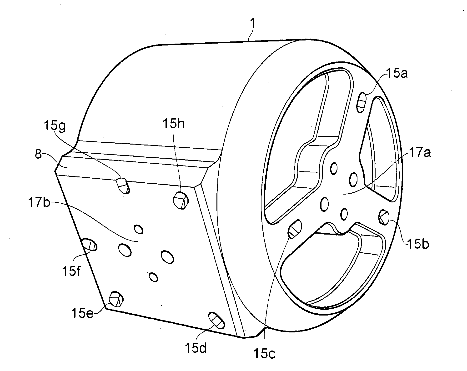
[0045]FIG. 3 shows an exploded view of a phantom 10 for use in calibrating images produced by an MRI scanner. The phantom 10 comprises a block 1 of plastics material, a lid 2, a flexible diaphragm 3, a cap 4 and a base plate 5. The block 1 is largely cylindrical but at one point the curved surface extends into a plinth 8

[0046]A series of elongate passages in the form of blind bores, e.g. 12, have been drilled into an end face of the block 1. The end face into which the bores extend is shown more clearly in FIG. 8. The bores all extend to the same depth and all have the same radius. As can be seen most clearly in FIG. 8, the bores are arranged in a pattern of concentric circles around a central one of their number, labelled 14. The surface in which the bores are formed is recessed slightly, such that a raised lip 6 is defined around this surface.

[0047]In use, the lid 2 is sealed onto the edge of the lip 6 thereby defining a cavity beneath the lid that is in fluid communication with a...


PUM


Abstract

A tomogram taken on an imaging path of a tomograph is corrected by using sets of tomogram correction data for neighbouring positions on that path, in an interpolative process. An error map of a tomograph is built up by comparing tomograms of a phantom with the expected appearance of the phantom at the tomogram positions. Also provided is a phantom having a body with one or more imaging fluid receptacles formed therein.

Description

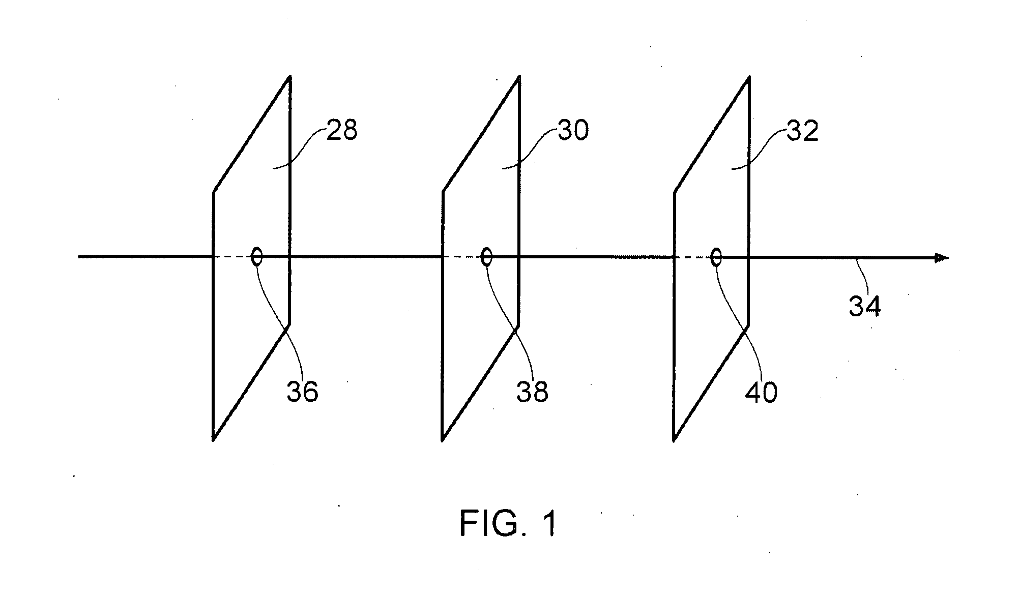
FIELD OF THE INVENTION[0001]The invention relates to the field of tomography.BACKGROUND[0002]In tomography, a device called a tomograph takes a series of 2D images, called tomograms, at various positions within an object. Often, these tomograms are combined using mathematical techniques to produce a 3D image, called a polytomogaph, of the internal structure of the object. A series of tomograms that are combined into a polytomograph of a target object are captured at different positions along an imaging path.[0003]Typically, the imaging path is an axis extending into the target object and the tomograms are images of 2D planes (slices) within the target object, each plane lying perpendicular to the imaging path and intersecting the imaging path at a respective capture position. Such a scheme is shown in FIG. 1, which illustrates three planes 28, 30 and 32 in which tomograms are captured. The planes 28, 30 and 32 are parallel to one another and all lie perpendicular to axis 34. The poi...

Claims


Application Information

Patent Timeline
Patent Type & Authority Applications(United States)
IPC IPC(8): G06K9/00
CPCG01R33/56572G01R33/58G06T11/008G06T5/006G06T7/0022G06T3/00G06T7/97G06T5/80
Inventor ASHTON, SHARON ANNDERRICK, HUGO GEORGEMORTIMER, JAMES DAVID
Owner RENISHAW (IRELAND) LTD
Learn More