Money handling apparatus

a technology for handling equipment and money, applied in the direction of de-stacking articles, electric actuation, instruments, etc., can solve the problems of troublesome teller, inability to deposit and disburse money, and interruption of conventional depositing and dispensing machines, so as to reduce the interruption period and improve the efficiency of handling money

Active Publication Date: 2011-08-18
GLORY KOGYO KK
View PDF5 Cites 8 Cited by
  • Summary
  • Abstract
  • Description
  • Claims
  • Application Information

AI Technical Summary

Problems solved by technology

In this case, conventional depositing and dispensing machines may experience the following disadvantage.
Specifically, when the escrow unit becomes full, the depositing cannot proceed.
Thus, in depositing a large amount of banknotes at a time in the conventional depositing and dispensing machine, the teller has to carry out a certain operation to take care of the apparatus every time when the escrow unit or the storage unit becomes full, which is troublesome to the teller.
Further, the depositing is interrupted every time when the teller carries out the operation, thereby increasing time required for the depositing.
This increases customers'waiting time, and decreases efficiency of transactions at teller's windows.
However, even when the capacity of the escrow unit is increased, some operation has to be performed during the depositing as described above when the amount of the deposited banknotes exceeds the increased capacity of the escrow unit.
Further, increase in capacity of the escrow unit in the casing increases the size of the apparatus.
The provision of the processing mechanism disadvantageously complicates the structure of the apparatus.
However, also in this case, the size of the apparatus increases.
However, this machine is merely a banknote processing machine which does not include the storage unit configured to store the banknotes, and cannot perform the depositing and the dispensing.
However, the same disadvantage occurs in the dispensing.
Such a disadvantage is not particular to the depositing / dispensing of the banknotes in / from the depositing and dispensing machine.
The same disadvantage may occur in depositing and dispensing coins.

Method used


Image

  • Money handling apparatus
  • Money handling apparatus
  • Money handling apparatus

Examples


Embodiment Construction

[0052]An embodiment of the present invention will be described in detail with reference to the drawings. The following preferred embodiment will be set forth merely for the illustration purpose, and are not intended to limit the scope, applications, and use of the invention.

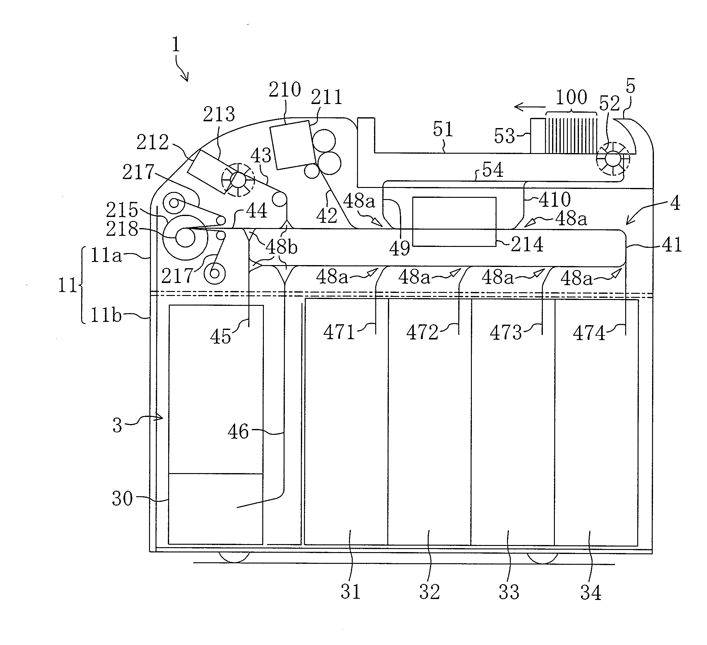
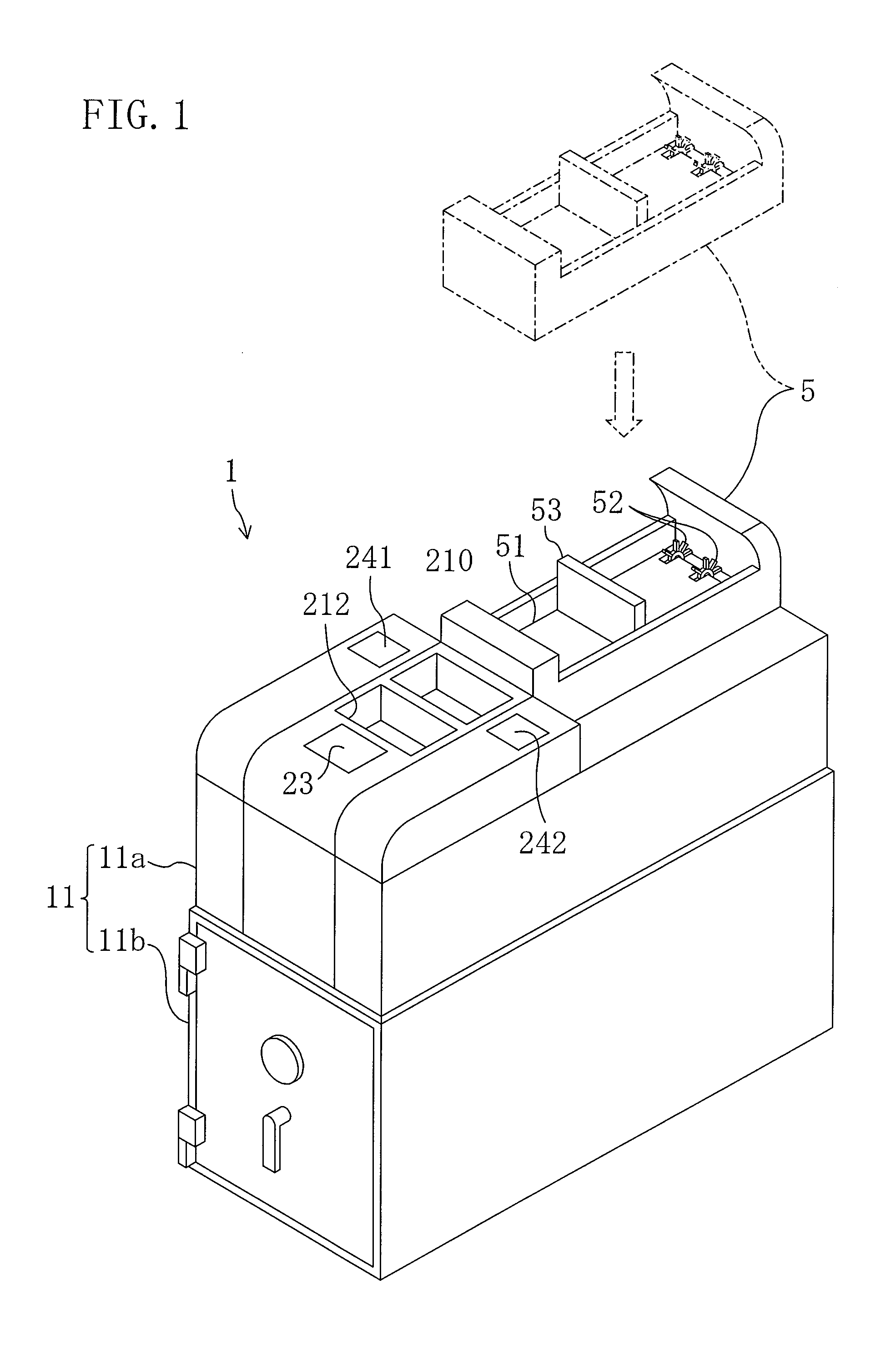
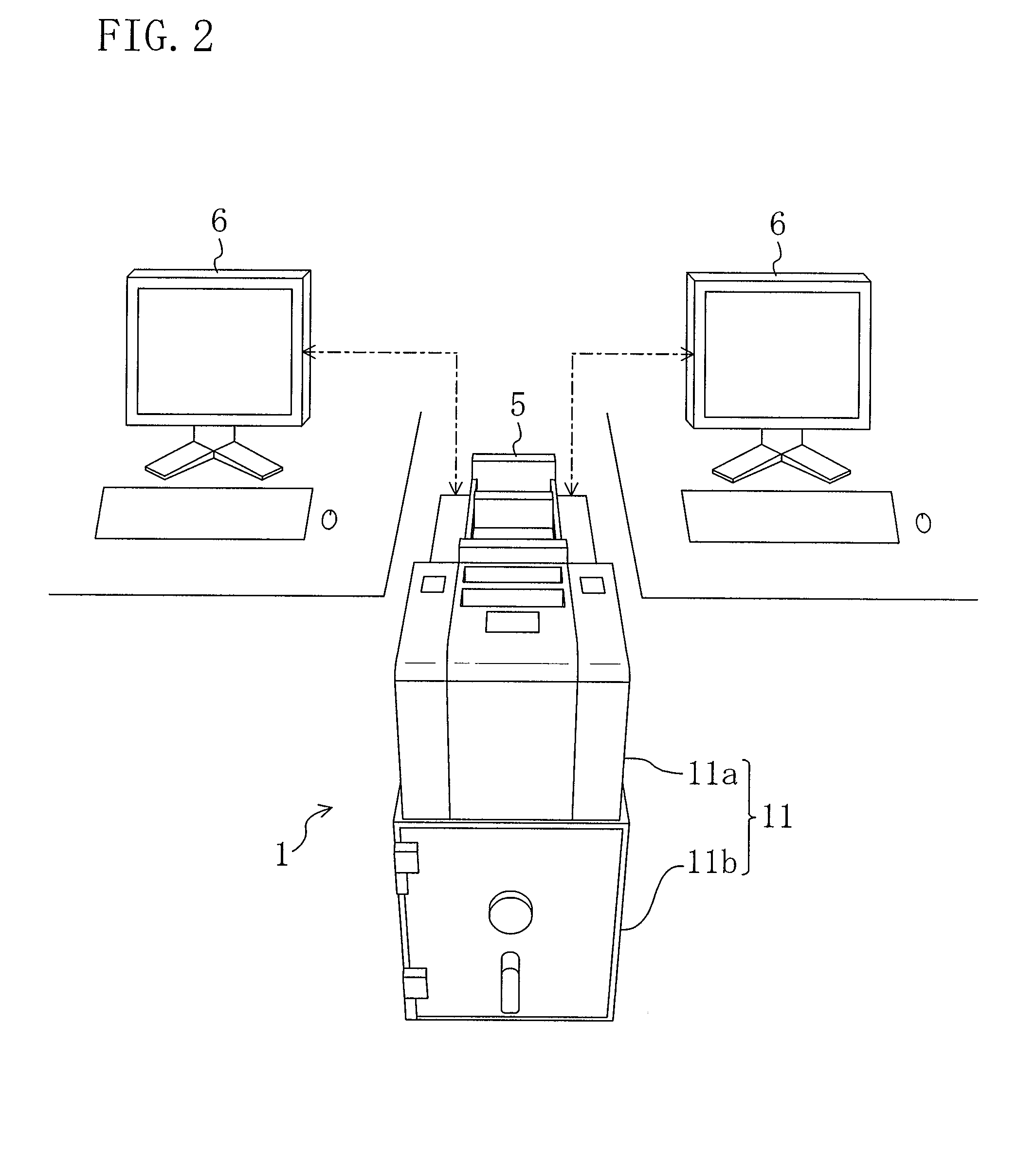
[0053]FIG. 1 is a perspective view illustrating a depositing and dispensing machine 1 as an example of a money handling apparatus. As shown in FIG. 2, the depositing and dispensing machine 1 is substantially in the shape of a rectangular box having a relatively short width, and a relatively long depth. For example, the depositing and dispensing machine 1 is placed in a teller counter of a bank, and is shared by two tellers on the right and left sides of the depositing and dispensing machine 1. Two higher-ranking terminals 6 used by the right and left tellers, respectively, are connected to the depositing and dispensing machine 1. The tellers use the depositing and dispensing machine 1 by operating the higher-rank...


PUM


Abstract

A money handling apparatus for performing at least depositing includes: a casing; a depositing unit; a recognition unit configured to at least count or recognize money fed from the depositing unit; an inner storage unit from which the money stored therein is unremovable directly from the outside of the casing; an outer stacking unit from which the money stacked therein is removable directly from the outside of the casing; a transport unit configured to transport the money among the above-described units; and a controller configured to allow selective transport of the money handled by the recognition unit to the inner storage unit, or the outer stacking unit. The controller transfers the money to the inner storage unit when a first deposit mode is selected by a selection signal, or transfers the money to the outer stacking unit when a second deposit mode is selected.

Description

TECHNICAL FIELD[0001]The present invention relates to a money handling apparatus for depositing and / or dispensing money.BACKGROUND ART[0002]Patent Document 1 discloses, for example, a depositing and dispensing machine which is placed in a teller counter of a bank, and is shared by two tellers on the right and left sides of the machine. The depositing and dispensing machine is a so-called circulating depositing and dispensing machine. Specifically, the machine includes, in a casing, a depositing unit in which banknotes are introduced, a recognition unit configured to count and recognize the banknotes, an escrow unit configured to temporarily retain the recognized banknotes, a storage unit configured to store the banknotes retained in the escrow unit after the deposit of the banknotes is confirmed, and a dispensing unit which is provided with a shutter, and from which the banknotes fed from the storage unit are dispensed in dispensing.[0003]The depositing and dispensing machine perfor...

Claims


Application Information

Patent Timeline
Patent Type & Authority Applications(United States)
IPC IPC(8): G06F7/00G07D13/00B65D83/08
CPCG07D11/006G07D11/0051G07D11/12G07D11/20G07D11/25
Inventor DOI, KAZUHIRO
Owner GLORY KOGYO KK
Why Eureka
Try Eureka