Printer

a printing machine and platen roller technology, applied in the field of printing machines, can solve the problems of occupying a large space, difficult to further reduce the diameter of the platen roller at present, poor workability, etc., and achieves the effects of easy operation, high reliability, and enhanced manipulation properties

a printing machine and platen roller technology, applied in the field of printing machines, can solve the problems of occupying a large space, difficult to further reduce the diameter of the platen roller at present, poor workability, etc., and achieves the effects of easy operation, high reliability, and enhanced manipulation properties

US20110203467A1Inactive Publication Date: 2011-08-25SEIKO INSTR INC

Image

  • Printer
  • Printer
  • Printer

Examples


Embodiment Construction

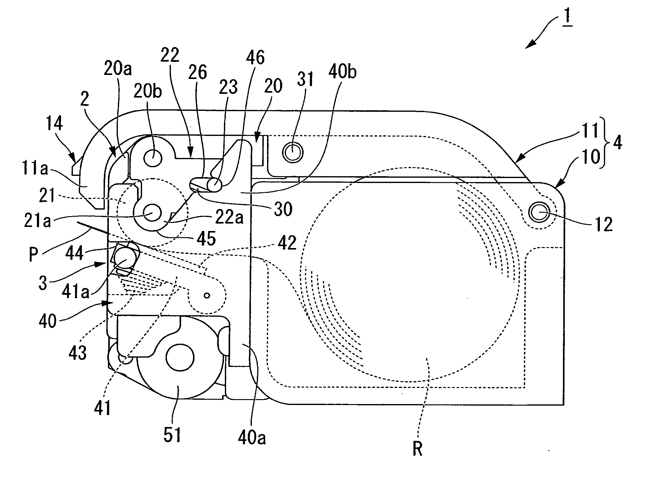
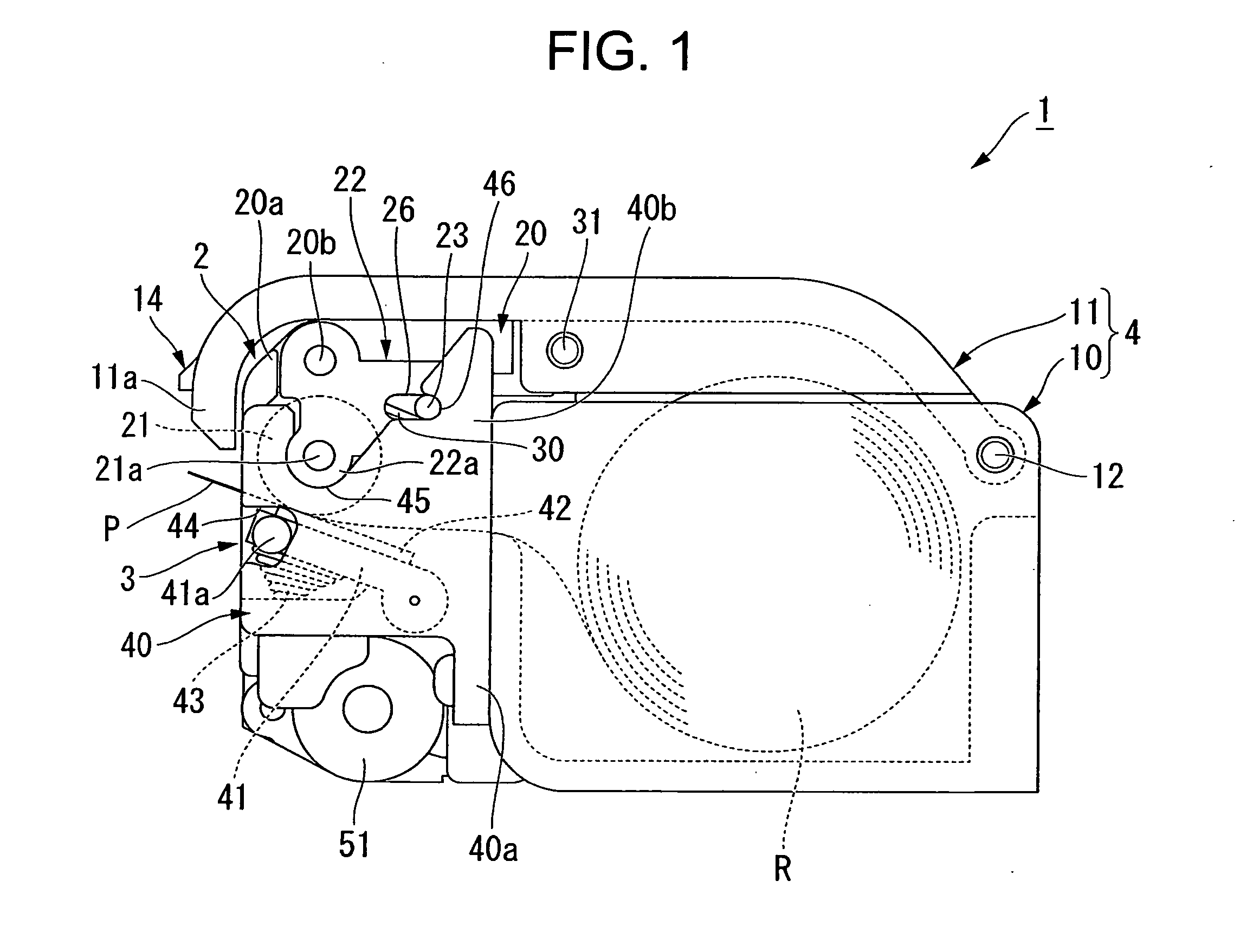
[0046]In the following, description is made of an embodiment according to the present invention with reference to FIGS. 1 to 12. Note that, in this embodiment, description is made of a thermal printer as an example of a printer.

[0047]As illustrated in FIGS. 1 and 2, a printer 1 according to this embodiment includes a platen unit 2 and a main unit 3 which are separably combined with each other and a casing 4 for accommodating a sheet roll R formed of a wound recording sheet P.

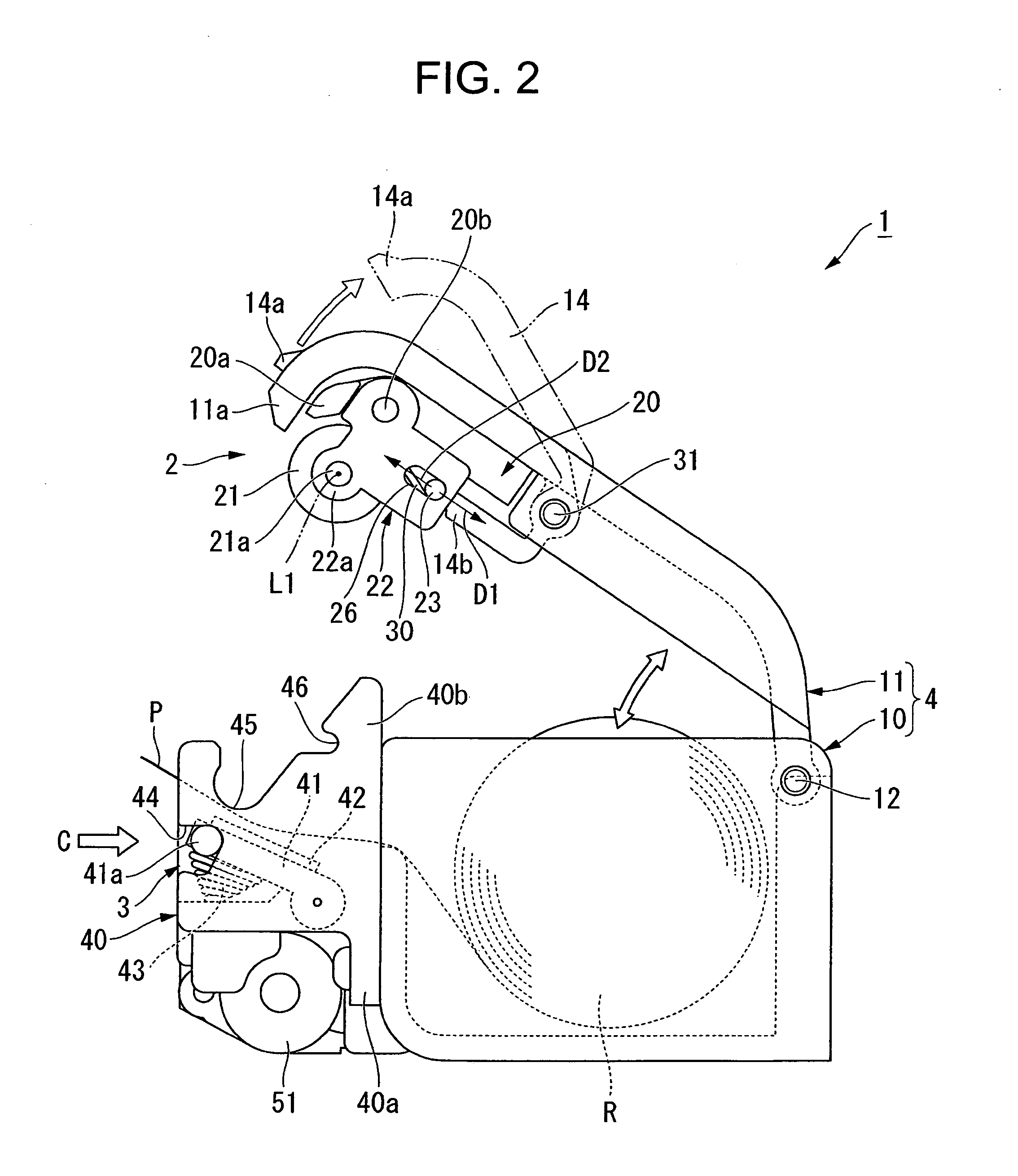
[0048]Note that, FIG. 1 is an overall side view of the printer 1 in a state in which the platen unit 2 and the main unit 3 are combined with each other. FIG. 2 is an overall side view illustrating a state in which the platen unit 2 and the main unit 3 in the state illustrated in FIG. 1 have been separated from each other.

[0049]First, description is made of the casing 4.

[0050]The casing 4 according to this embodiment includes a base member 10 and a lid member 11 openably and closably (rotatably) coupled to the ba...


PUM


Abstract

Provided is a printer in which attachment and detachment manipulation of a platen roller can easily be performed, in which the platen roller can be retained with high reliability at a time of attachment, and in which downsizing of the entire printer is achieved due to use of the platen roller smaller in diameter. A printer (1) includes: a rocking plate (22) including a bearing portion (22a) for axially supporting a platen roller (21); a rock shaft (23) inserted through a slide opening portion (26) so as to be combined with the rocking plate; and a stationary frame (40) to which a recording head (42) is fixed, in which: the rock shaft is slidingly movable in an imaginary in-plane direction orthogonal to a platen axis; the stationary frame includes a first recess (45) into which the bearing portion is disengageably fitted, and a second recess (46) into which, after the bearing portion is fitted, the rock shaft is disengageably fitted; and the bearing portion is undisengageable from inside the first recess while the rock shaft is fitted, and is disengageable from inside the first recess after the rock shaft is disengaged.

Description

1. FIELD OF THE INVENTION[0001]The present invention relates to a printer in which a platen roller and a recording head are separably combined with each other.2. DESCRIPTION OF THE RELATED ART[0002]As conventionally known printers, there are given printers in which a recording head and a platen roller held in contact with the recording head are provided inside a casing, and in which the recording head performs recording onto a recording sheet sent out by the platen roller. In the printers of this type, for example, at the time of setting of the recording sheet or jam treatment, or at the time of maintenance or replacement of the recording head, the platen roller, and the like, the recording head and the platen roller remain in contact with each other inside the casing. Thus, workability is poor.[0003]In view of this, it is desired that the recording head and the platen roller can be spaced apart from each other so as to be exposed to an outside of the casing. In particular, the reco...

Claims


Application Information

Patent Timeline
25 Aug 2011
Publication
US20110203467A1
IPC
B41F5/00
CPC
B41J11/04; B41J3/4075
Inventors
NAITO, AKIO