Evaporated fuel treatment apparatus and method of detecting failure in control valve

a technology of evaporation fuel treatment and control valve, which is applied in the direction of combustion air/fuel air treatment, electric control, instruments, etc., to achieve the effect of shortening the waiting tim

Inactive Publication Date: 2011-08-25
HONDA MOTOR CO LTD
View PDF9 Cites 22 Cited by
  • Summary
  • Abstract
  • Description
  • Claims
  • Application Information

AI Technical Summary

Benefits of technology

[0011]The present invention may provide an evaporated fuel treatment apparatus which can shorten the waiting time until a driver, etc., becomes able to open the filler cap at the time of fueling.
[0018]According to this configuration, prior to the opening control on the control valve, the opening angle of the control valve is increased from substantially zero to the predetermined opening angle in the dead-zone range and this condition is maintained, so that at the time of opening control, an operation of increasing the opening angle from substantially zero to the predetermined opening angle in the dead-zone range can be omitted, and the opening angle can be increased from the predetermined opening angle. Accordingly, the pressure inside the fuel tank can be reduced rapidly, and a waiting time until a driver, etc., becomes able to open a filler cap at the time of fuel charging can be shortened.
[0019]Alternatively, by changing the open speed within a range from substantially zero to around the predetermined opening angle in the dead-zone range, the pressure inside the fuel tank can be reduced rapidly, and thus the waiting time until the driver, etc., becomes able to open the filler cap at the time of fuel charging can be shortened.
[0021]According to this configuration, at the time of opening control, the opening angle increases from the substantially maximum opening angle in the dead-zone range through substantially no dead-zone range, so that the pressure inside the fuel tank can be reduced rapidly, and the waiting time until the driver, etc., becomes able to open the filler cap at the time of fuel charging can be shortened. The term substantially maximum opening angle means that such an opening angle has a margin around the maximum opening angle in consideration of a varying of an opening angle detecting unit (an encoder).
[0023]According to this configuration, the initial part of the dead-zone range is set to correspond to a fast open speed, and the remaining part of the dead-zone range and the following range are set to correspond to a normal control open speed which is reduced from the fast open speed, so that the control valve can be opened rapidly. Accordingly, the control valve can flow the evaporated fuel rapidly, so that the pressure inside the fuel tank can be reduced rapidly, and the waiting time can be shortened.
[0029]According to the present invention, it becomes possible to detect a seizing failure of the control valve.

Problems solved by technology

However, an opening / closing operation of the control valve causes the canister to adsorb the evaporated fuel, so that in the case of a vehicle which does not run the engine for a long time like a plug-in hybrid vehicle, such a vehicle needs a canister with a further large capacity.

Method used


Image

  • Evaporated fuel treatment apparatus and method of detecting failure in control valve
  • Evaporated fuel treatment apparatus and method of detecting failure in control valve
  • Evaporated fuel treatment apparatus and method of detecting failure in control valve

Examples


first embodiment

[0063]FIG. 4 shows a flowchart of an evaporated fuel treating method executed by the evaporated fuel treatment apparatus 1 according to the first embodiment of the present invention.

[0064]The control unit 2 starts (is activated) upon turning on of the IG (ignition) switch of the vehicle, etc., equipped with the evaporated fuel treatment apparatus 1.

[0065]The control unit 2 determines in step S1 whether or not the IG (ignition) switch is turned off. When the IG switch is turned off (step S1: YES), the flow of the process along this flowchart is terminated, and when the IG switch is not turned off (step S1: NO), the process progresses to step S3.

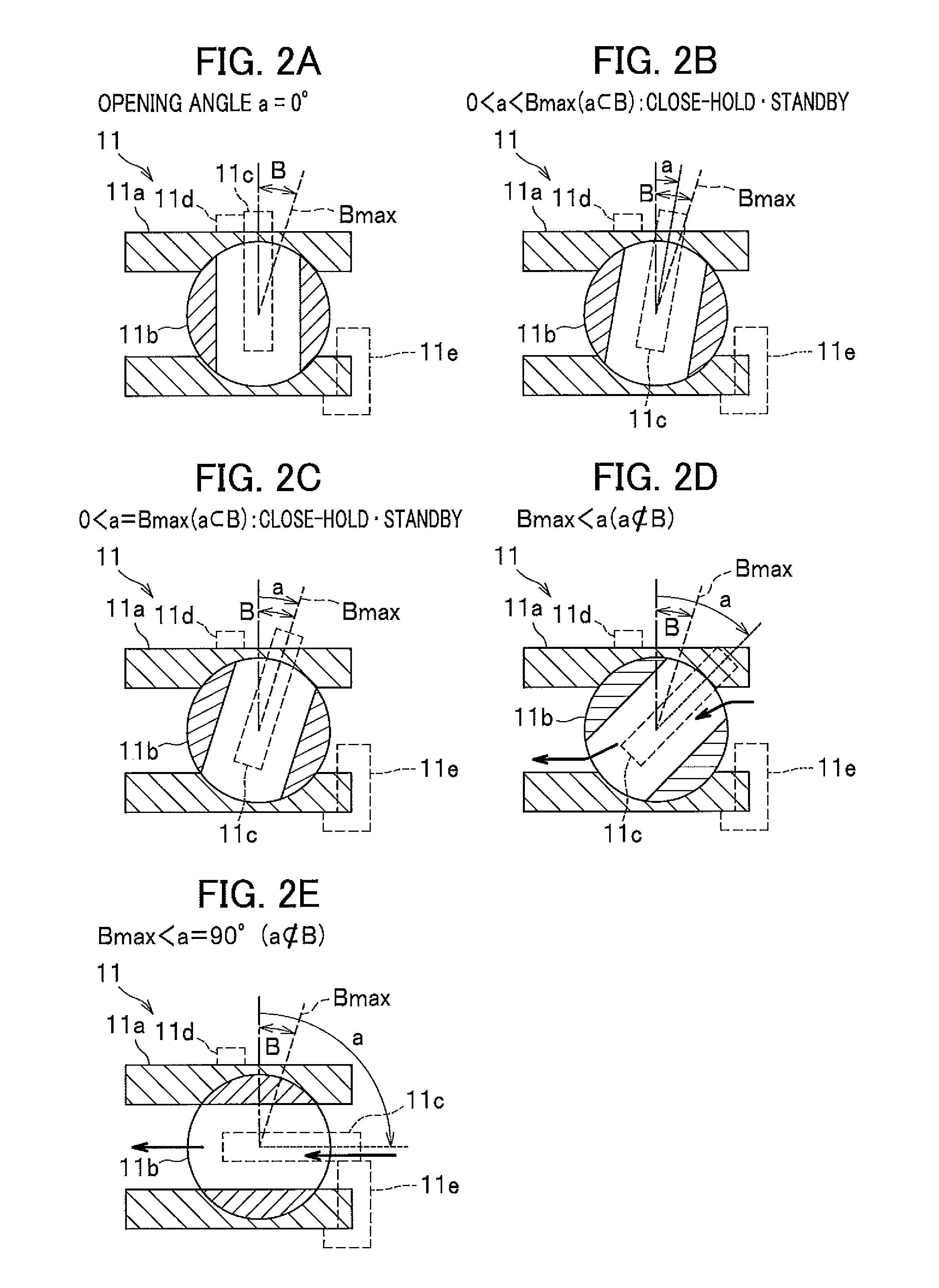
[0066]The control unit 2 executes zero point correction in step S2 in order to prevent the ball (the valve element) 11b from being seized. According to the zero point correction, the valve is closed until the stem 11c abuts the stopper 11d, etc., and the opening angle a at which the ball 11b is stopped is set as a zero point.

[0067]As shown in ...

second embodiment

[0088]FIG. 8 shows a flowchart of an evaporated fuel treating method executed by an evaporated fuel treatment apparatus 1 according to a second embodiment.

[0089]The control unit 2 is started (activated) upon turning on of the IG (ignition) switch of the vehicle, etc. equipped with the evaporated fuel treatment apparatus 1.

[0090]In step S201, the control unit 2 executes zero point correction which is also for preventing the ball (the valve element) 11b from being seized. According to the zero point correction, the valve is closed until the stem 11c abuts the stopper 11d, etc., and the opening angle a at which the ball 11b is stopped is set as the zero point. The opening angle a is changed within the dead-zone range B (the opening angle a is increased), and then the zero point correction (the opening angle a is decreased) is performed. The increase and decrease of the opening angle a prevents the ball (the valve element) 11b from being seized.

[0091]The control unit 2 determines in ste...

third embodiment

[0112]Next, an explanation will be given of a failure detecting method executed by an evaporated fuel treatment apparatus 1 according to a third embodiment of the present invention.

[0113]>

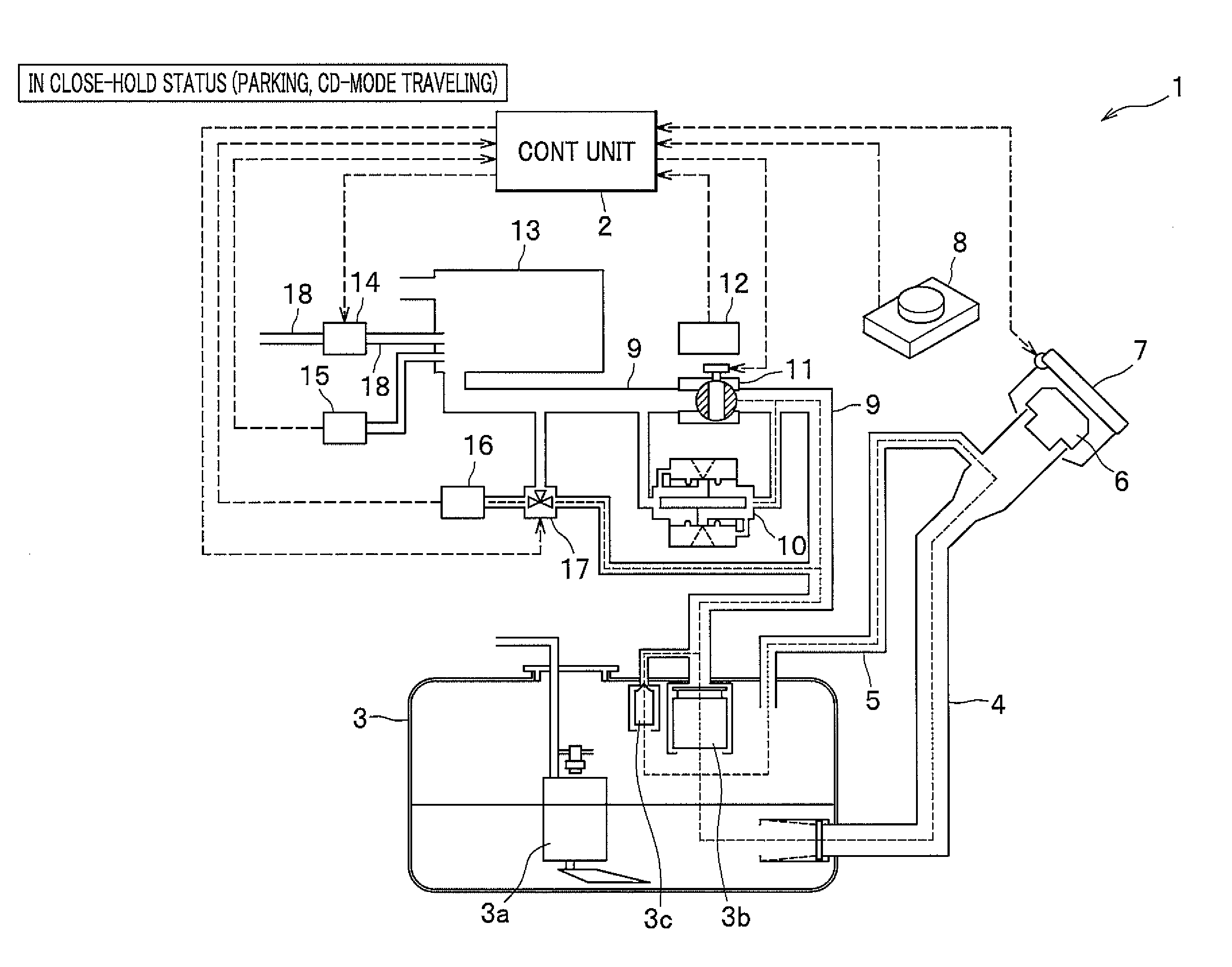
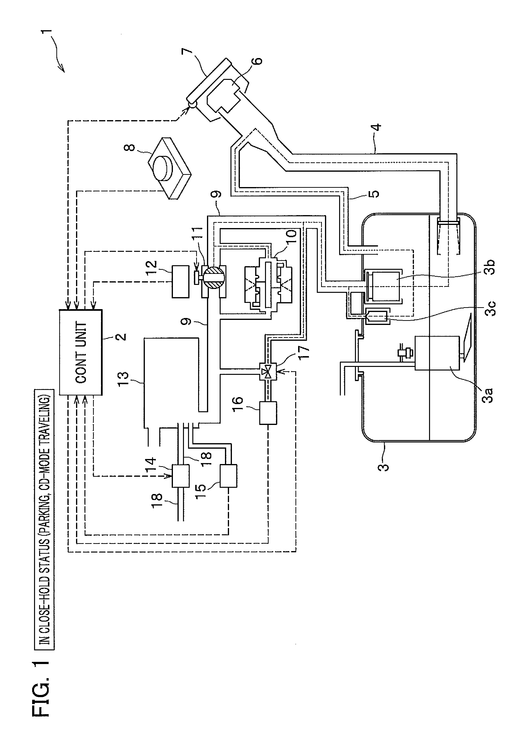
[0114]Vehicles such as plug-in hybrid vehicles which do not run the engine for a long time do not have the “CS MODE driving” (purging) status (see FIG. 7) and do not become the “fuel charging” status (see FIG. 6) if the fuel is not consumed. Accordingly, the status in which the control valve 11 is closed for a long time (see FIG. 1) is maintained, and thus the control valve 11 may be seized in some cases.

[0115]When the control valve 11 is seized, it is difficult to run the large amount of evaporated fuel (vapor) to flow into the canister 13 at the time of fuel charging (see FIG. 6), so that the evaporated fuel may leak from the fuel lid 7, and it is desirable to perform failure detecting control for detecting the seizing failure of the control valve 11.

[0116]Also, if the engine is not run, the evap...


PUM


Abstract

An evaporated fuel treatment apparatus including a canister for adsorbing an evaporated fuel in a fuel tank, a control valve at a vapor path communicating with a fuel tank and a canister, has a dead-zone range where a flow of the evaporated fuel is blocked even if an opening angle of the control valve is increased in an open direction from zero opening angle, and allows the evaporated fuel to flow through over the dead-zone range. The control unit increases the opening angle from substantially zero to a predetermined angle in the dead-zone range and stands by prior to the opening control, and increases the opening angle from the predetermined angle upon the opening control. An output value by control unit set in the dead-zone range is compared with a detected value to detect a failure of the control valve.

Description

CROSS REFERENCE TO RELATED APPLICATION[0001]This application claims the foreign priority benefit under Title 35, United States Code, §119(a)-(d) of Japanese Patent Applications No. 2010-035088, No. 2010-035136, and No. 2010-035137, filed on Feb. 19, 2010 in the Japan Patent Office, the disclosures of which are herein incorporated by reference in their entirety.BACKGROUND OF THE INVENTION[0002]1. Field of the Invention[0003]The present invention relates to an evaporated fuel treatment apparatus which has a canister for adsorbing an evaporated fuel produced in a fuel tank and which treats the evaporated fuel and relates to a control method for a control valve provided at a communication path (a vapor path) between the fuel tank and the canister of the evaporated fuel treatment apparatus, and more particularly, relates to a method of detecting a failure in the control valve.[0004]2. Description of the Related Art[0005]Conventional evaporated fuel treatment apparatuses cause a canister ...

Claims


Application Information

Patent Timeline
Patent Type & Authority Applications(United States)
IPC IPC(8): F02M33/02G01M13/00
CPCF02D41/0032F02D41/221Y02T10/40F02M25/0836F02M25/0809
Inventor HORIBA, AYUMUKITAMOTO, MASAKAZUHIDANO, KOICHISAIGA, JUNJI
Owner HONDA MOTOR CO LTD
Why Eureka
Try Eureka