Wind power generation system and operation control method thereof

Active Publication Date: 2011-08-25
MITSUBISHI HEAVY IND LTD
View PDF12 Cites 28 Cited by
  • Summary
  • Abstract
  • Description
  • Claims
  • Application Information

AI Technical Summary

Benefits of technology

[0017]According to the present invention, an advantage is afforded in that

Problems solved by technology

However, if the correlation of the output fluctuations of each wind turbine in the wind farm is high, there is a risk

Method used


Image

  • Wind power generation system and operation control method thereof
  • Wind power generation system and operation control method thereof
  • Wind power generation system and operation control method thereof

Examples


Embodiment Construction

[0028]In the following, one embodiment of a wind power generation system and an operation control method thereof according to the present invention will be described with reference to the drawings.

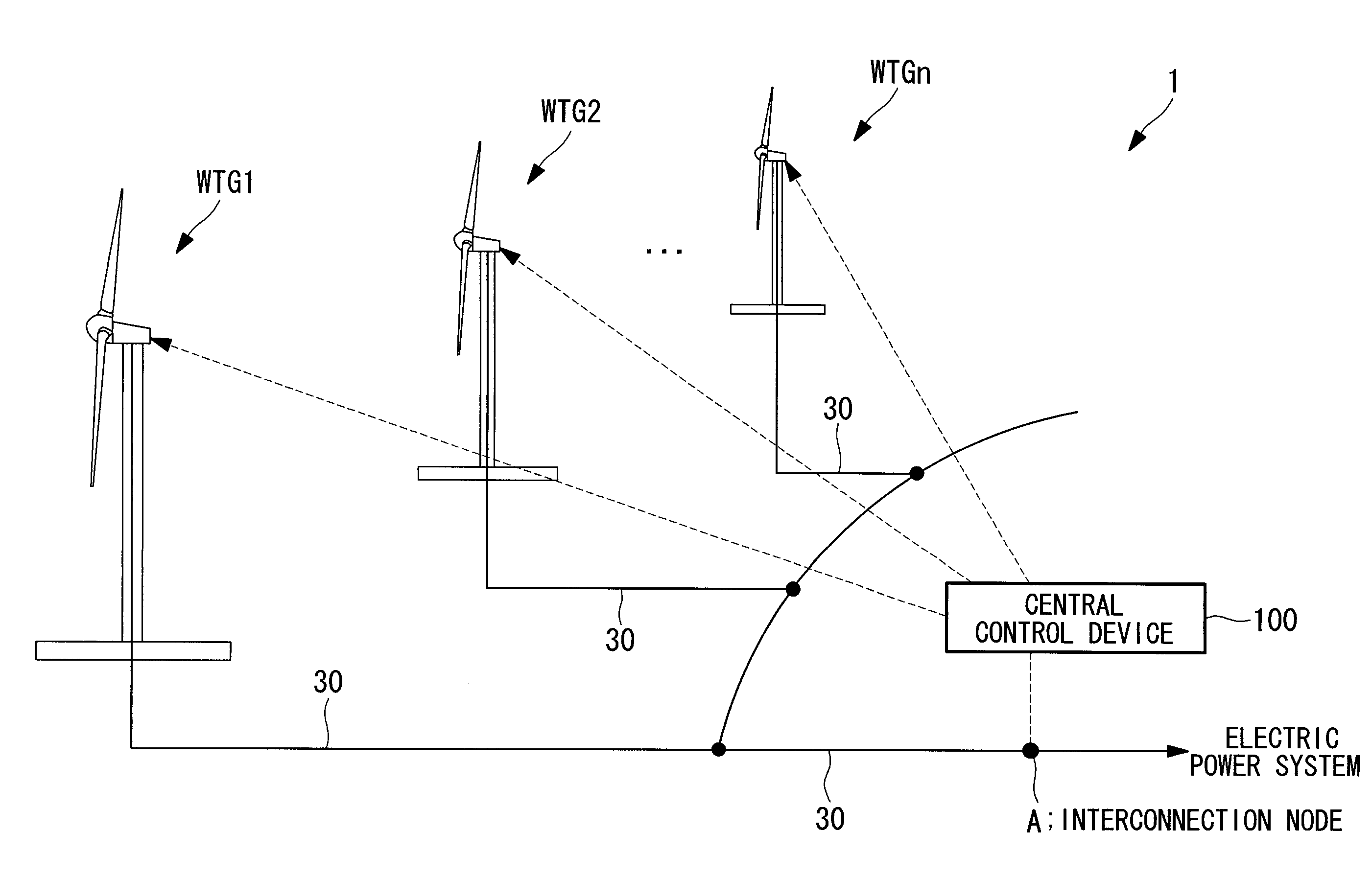
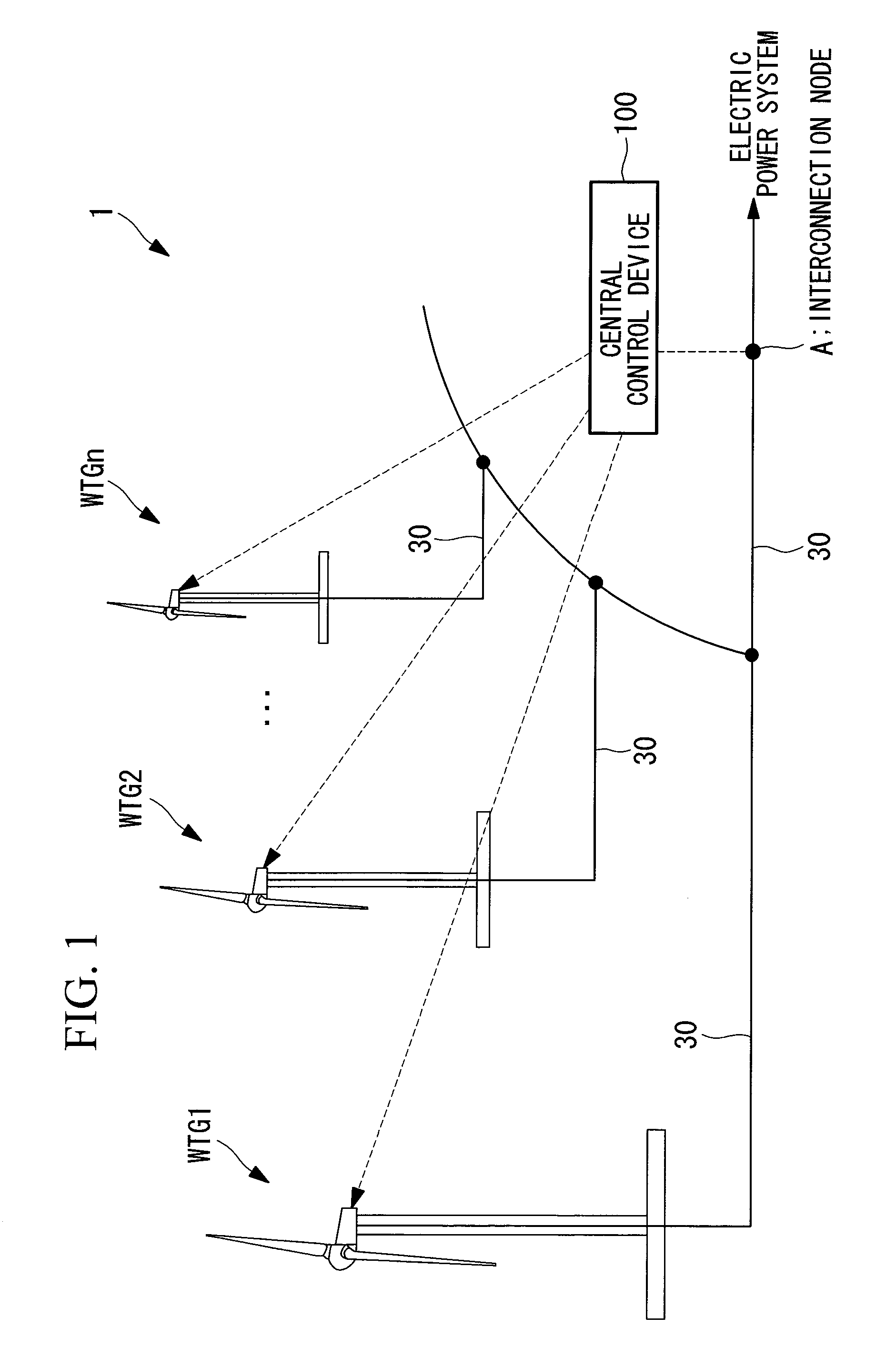
[0029]FIG. 1 is a block diagram showing the overall configuration of a wind power generation system according to this embodiment. As shown in FIG. 1, a wind power generation system 1 is provided with a plurality of wind turbines WTG1, WTG2, . . . , WTGn (hereinafter, when referring to all wind turbines, they will be simply assigned the reference sign “WTG”, and when referring to each wind turbine individually, they will be assigned reference signs “WTG1”, “WTG2”, and so forth) and a central control device 100 that gives a control command to the each wind turbine WTG. In this embodiment, each wind power generator WTG may be either a variable-speed wind turbine or a constant-speed wind turbine.

[0030]The output power of the each wind turbine WTG1, WTG2, WTGn is supplied to an electric power s...


PUM


Abstract

The object is to reduce an output fluctuation in an interconnection node. Provided is an operation control method of a wind power generation system including a step of obtaining the output data of each wind turbine, a step of determining a correlation between output fluctuations of adjacent wind turbines by using output data, and a step of shifting, if a strong correlation is exhibited, a phase of output fluctuation of either one of the adjacent wind turbines by a period at which the strong correlation is exhibited.

Description

TECHNICAL FIELD[0001]The present invention relates to a wind power generation system and an operation control method thereof.BACKGROUND ART[0002]Smoothing output fluctuations of a wind farm is known. If the standard deviation of the output fluctuation of one wind turbine is defined as σ, then the standard deviation σtotal total of the output fluctuation of a wind farm with M wind turbines is represented by the following equation (1) provided that the output fluctuations of each wind turbine are not correlated (random).[Equation 1]σtotal=σ√{square root over (M)}  (1)[0003]Patent Citation 1: U.S. Pat. No. 6,724,097, specification[0004]Patent Citation 2: U.S. Pat. No. 6,946,751, specificationDISCLOSURE OF INVENTION[0005]However, if the correlation of the output fluctuations of each wind turbine in the wind farm is high, there is a risk that the output fluctuation of the wind farm will not be smoothed, but will be observed as a large output fluctuation.[0006]The present invention has be...

Claims


Application Information

Patent Timeline
IPC IPC(8): H02P9/04
CPCF03D7/0272F03D7/028F03D7/048H02P2101/15H02P9/04Y02E10/723F05B2270/1033Y02E10/72
Inventor ARINAGA, SHINJIMATSUSHITA, TAKATOSHIWAKASA, TSUYOSHISHIBATA, MASAAKIYASUGI, AKIRA
Owner MITSUBISHI HEAVY IND LTD
Why Eureka
Try Eureka