System and method for providing collaborating power controllers

a technology of power controllers and collaborating power, applied in the field of power management, can solve the problems of significant challenges for power system administrators, component manufacturers, service providers, and energy grid operators, and the ability to properly manage energy resources

Inactive Publication Date: 2011-08-25
CISCO TECH INC
View PDF28 Cites 151 Cited by
  • Summary
  • Abstract
  • Description
  • Claims
  • Application Information

AI Technical Summary

Problems solved by technology

However, in practical terms, energy waste occurs due to the prevalence of reactive power.
The challenge lies in successfully coordinating these power management activities in a manner that minimizes/eliminates pot...

Method used


Image

  • System and method for providing collaborating power controllers
  • System and method for providing collaborating power controllers
  • System and method for providing collaborating power controllers

Examples


example embodiments

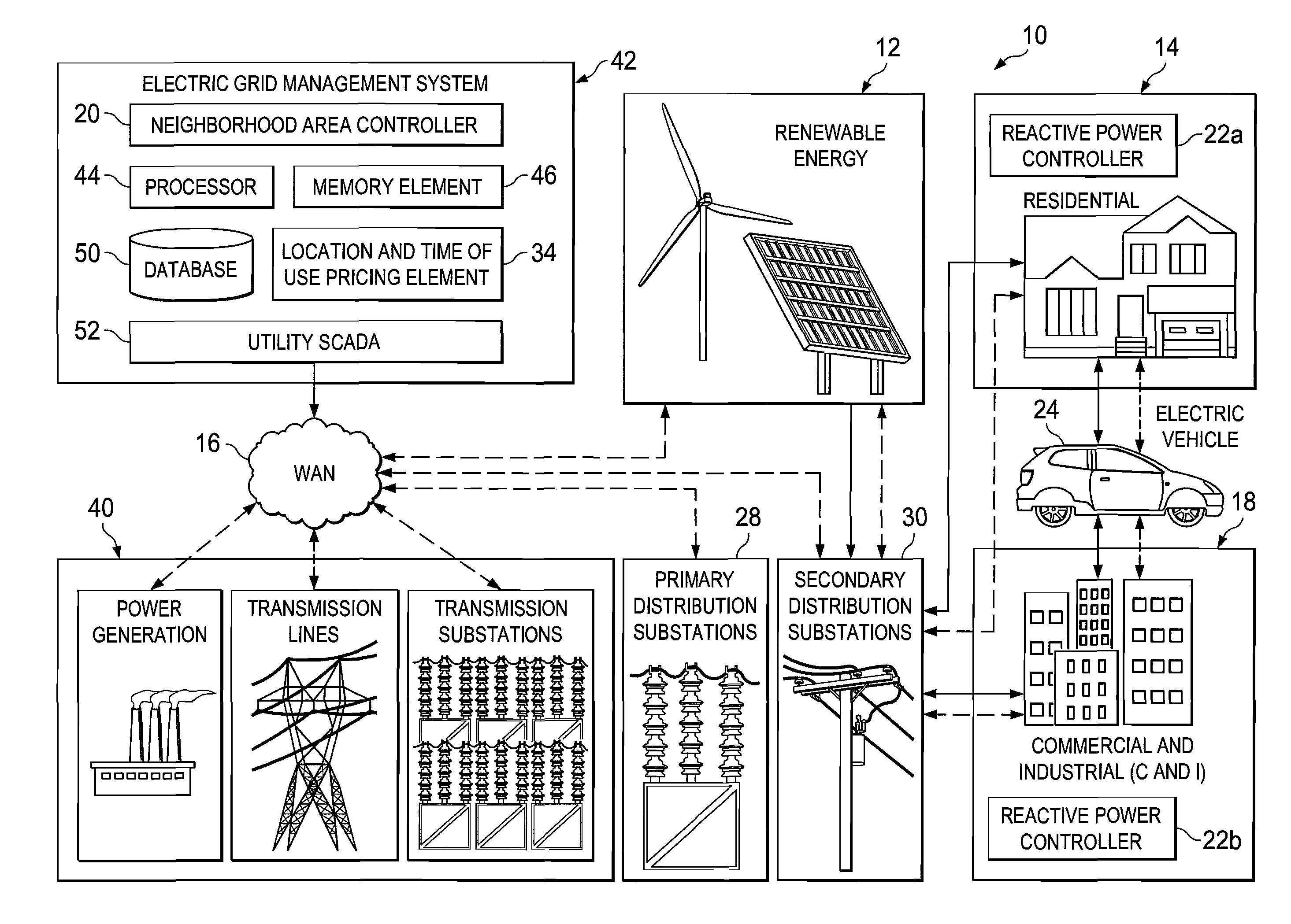
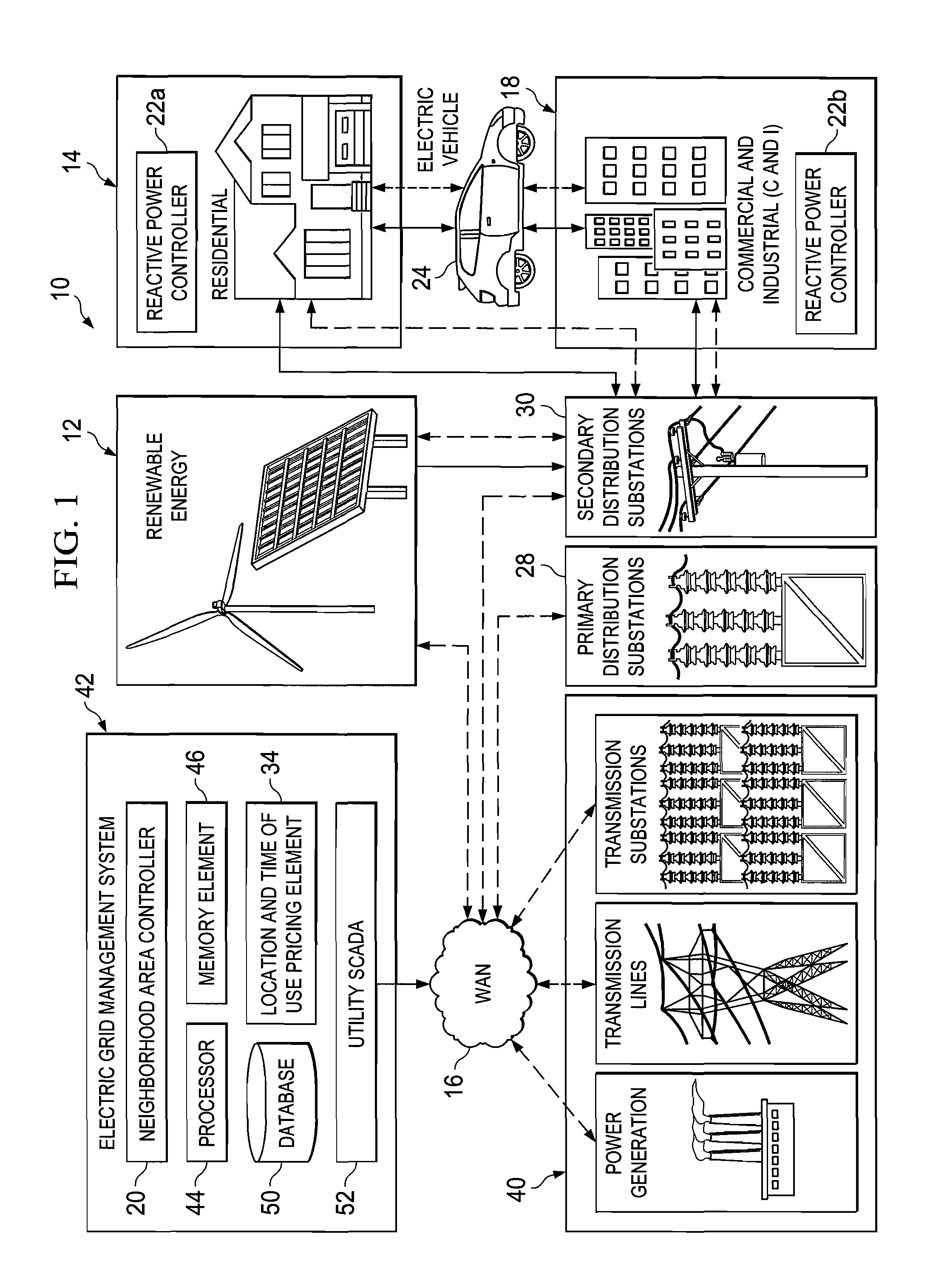
Turning to FIG. 1, FIG. 1 is a simplified block diagram of a system 10 for providing collaborating power controllers in accordance with one embodiment of the present disclosure. System 10 can include multiple residential consumers 14, along with multiple commercial and industrial consumers 18. In one example implementation, residential consumers 14 and commercial and industrial consumers 18 include respective reactive power controllers 22a-b. As an example of an object that may consume / receive power, an electric car 24 is also illustrated in FIG. 1, where electric car 24 can be used (and systematically charged) by components associated with residential or commercial entities. FIG. 1 also includes a renewable energy source 12, which may include items such as windmills, solar panels, geothermal mechanisms, biofuels, hydroelectricity, or any other suitable energy supply. Also provided in FIG. 1 is a wide area network (WAN) 16, which can connect an electric grid 40 to an electric grid m...


PUM


Abstract

A method is provided in one example embodiment and includes receiving a message associated with a detection of reactive power in an energy system and inducing a first quantity of reactive power at a power level specified in the message. The first quantity of reactive power is induced in order to mitigate a second quantity of reactive power that is detected on a specific segment of the energy system. The first quantity of reactive power is induced at a local level on which a source associated with the second quantity of reactive power operates. In more specific embodiments, the message is sent in response to a sensor detecting the second quantity of reactive power, where the first quantity and the second quantity of reactive power are the same. In other embodiments, the method can include receiving a second message to stop mitigating the first quantity of reactive power.

Description

TECHNICAL FIELDThis disclosure relates in general to the field of power management and, more particularly, to providing collaborating power controllers.BACKGROUNDEnergy consumption has become increasingly important in today's society. An electrical grid represents an interconnected power network, which can be used to deliver electricity to consumers. Activities for the electric grid can involve electricity generation, electric power transmission, and electricity distribution. A transmission network has the ability to move power across distances until it reaches its intended customer, which may be a company that owns a local distribution network. After arrival at a substation, power can be stepped down in voltage (from a transmission level voltage to a distribution level voltage). The power can then exit the substation and subsequently enter into distribution pathways. Thereafter, power can be delivered to a service location, where the power is stepped down again from the distributio...

Claims


Application Information

Patent Timeline
IPC IPC(8): G05F1/70
CPCG06Q40/04G07F15/008H02J3/008H02J3/18H02J3/382Y02E10/763Y04S50/10H02J3/383H02J3/386Y02E10/563Y02E40/30H02J2300/40H02J2300/28H02J2300/20H02J2300/24H02J3/381Y02E10/56Y02E10/76
Inventor SHAFFER, SHMUEL
Owner CISCO TECH INC
Why Eureka
Try Eureka