Non-reciprocal circuit element

a circuit element and non-reciprocal technology, applied in the field of non-reciprocal circuit elements, can solve the problems of communication failure, increase in insertion loss, increase in number of components, etc., and achieve the effect of increasing the number of components, preventing interference with the first isolator having a high passing frequency band, and increasing insertion loss and the number of components

Active Publication Date: 2011-08-25
MURATA MFG CO LTD
View PDF3 Cites 7 Cited by
  • Summary
  • Abstract
  • Description
  • Claims
  • Application Information

AI Technical Summary

Benefits of technology

[0012]In the non-reciprocal circuit element according to a preferred embodiment of the present invention, the input portions of the first and second isolators are electrically connected to define a single input port. Therefore, the non-reciprocal circuit element functions as a single non-reciprocal circuit element. In addition, a low pass filter is provided between the input port and the input portion of the second isolator. Therefore, the harmonic frequency band is attenuated in the second isolator having a low passing frequency band. As a result, interference with the first isolator having a high passing frequency band can be prevented. The low pass filter is disposed at a single position between the input port and the input portion of the second isolator. Therefore, increases in the insertion loss and the number of components can be prevented.
[0013]According to a preferred embodiment of the present invention, operations can be performed in a plurality of frequency bands and increases in the number of components and insertion loss can be prevented.

Problems solved by technology

This causes a communication failure.
However, when four phase converter circuits are provided to increase the operation frequency band, the insertion loss increases.
In addition, the number of components also increases, which makes it difficult to achieve reduction in size.

Method used


Image

  • Non-reciprocal circuit element
  • Non-reciprocal circuit element
  • Non-reciprocal circuit element

Examples


first preferred embodiment

FIGS. 1 to 8

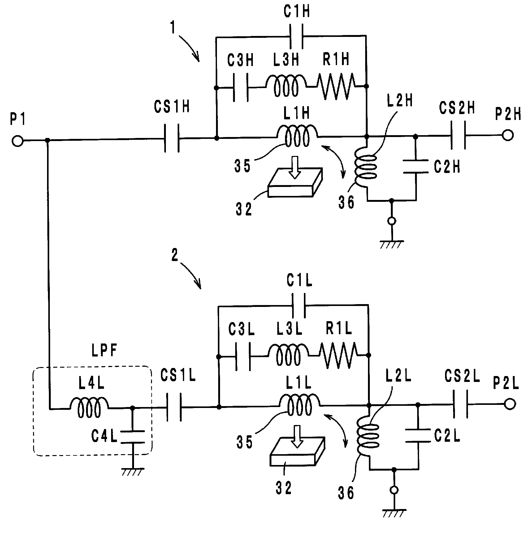
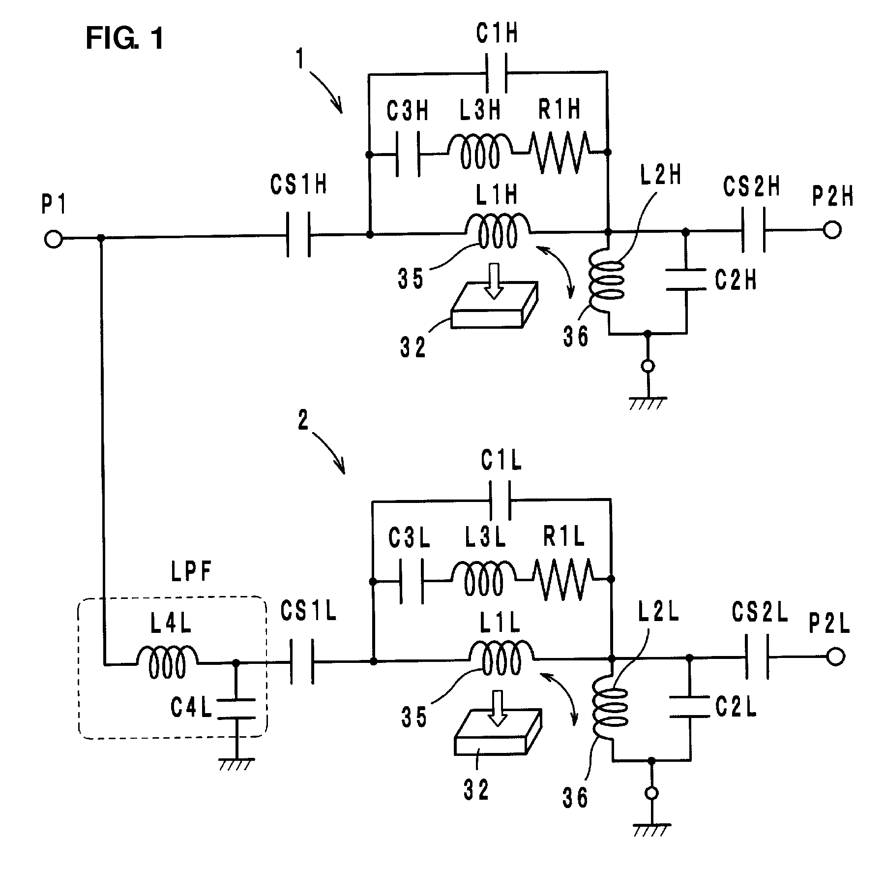
[0030]FIG. 1 illustrates an equivalent circuit of a non-reciprocal circuit element according to the first preferred embodiment of the present invention. Referring to FIG. 1, the non-reciprocal circuit element includes a first two-port isolator 1 and a second two-port isolator 2 that are integrated as a unit. The first and second isolators 1 and 2 preferably are lumped constant isolators, and are preferably configured such that first center electrodes 35 that define inductors L1H and L1L and second center electrodes 36 that define inductors L2H and L2L are arranged on ferrite bodies 32 so as to cross each other in an insulated state.

[0031]A passing frequency band f1 of the first isolator 1 is preferably set to be higher than a passing frequency band f2 of the second isolator 2. Input portions of the first and second isolators 1 and 2 are connected to each other as a single input port P1, and output portions thereof serve as output ports P2H and P2L. A low pass filter LPF ...

second preferred embodiment

FIG. 9

[0045]Referring to FIG. 9, a non-reciprocal circuit element according to a second preferred embodiment basically has a circuit structure similar to that of the first preferred embodiment, except the LC series resonant circuit (inductors L3H and L3L and capacitors C3H and C3L) is removed from the equivalent circuit illustrated in FIG. 1. The L-type low pass filter LPF is provided between the input port P1 and the input portion of the second isolator 2, and provides an operational effect similar to that in the first preferred embodiment.

third preferred embodiment

FIG. 10

[0046]Referring to FIG. 10, a non-reciprocal circuit element according to a third preferred embodiment basically has a circuit structure similar to that of the first preferred embodiment, except impedance adjusting capacitors CAH and CAL and a capacitor CJH are additionally provided. The impedance adjusting capacitors CAH and CAL are connected between the ground and the ends of the first center electrodes 35. The capacitor CJH is provided between the input portion and the output portion of the first isolator 1 to adjust the insertion loss and isolation. The L-type low pass filter LPF is provided between the input port P1 and the input portion of the second isolator 2, and provides an operational effect similar to that in the first preferred embodiment.


PUM


Abstract

A non-reciprocal circuit element includes first and second isolators of a high-pass type, each of the first and second isolators including a permanent magnet, a ferrite body to which a direct-current magnetic field is applied by the permanent magnet, and first and second center electrodes arranged on the ferrite body so as to cross each other in an insulated state. The first isolator has a passing frequency band that is higher than a passing frequency band of the second isolator. The first and second isolators include input portions that are electrically connected to define a single input port. A low pass filter is provided between the input port and the input portion of the second isolator.

Description

BACKGROUND OF THE INVENTION[0001]1. Field of the Invention[0002]The present invention relates to non-reciprocal circuit elements, and more particularly, to a non-reciprocal circuit element, such as an isolator or a circulator, used in a microwave band.[0003]2. Description of the Related Art[0004]Non-reciprocal circuit elements, such as isolators and circulators, have characteristics of transmitting signals only in a certain predetermined direction and not in the opposite direction. These characteristics of isolators, for example, are used in transmitter circuits of mobile communication devices, such as automobile phones and mobile phones.[0005]Japanese Patents Nos. 4155342 and 4197032 describe two-port isolators used as non-reciprocal circuit elements of the above-described type. The two-port isolators have the basic structure in which a first center electrode and a second center electrode are arranged on a surface of a ferrite body so as to cross each other in an insulated state. A...

Claims


Application Information

Patent Timeline
Patent Type & Authority Applications(United States)
IPC IPC(8): H01P1/36
CPCH01P1/387H01P1/36H01P3/08H01P1/38
Inventor WADA, TAKAYA
Owner MURATA MFG CO LTD
Why Eureka
Try Eureka