Information processor and control network system

a technology applied in the field of information processor and control network system, can solve the problems of time restriction on the control process, additional processes, and the inability to fully utilize the ethercat time synchronization function, so as to improve the accuracy of time synchronization and facilitate software development.

Active Publication Date: 2011-08-25
HITACHI IND EQUIP SYST CO LTD
View PDF11 Cites 48 Cited by
  • Summary
  • Abstract
  • Description
  • Claims
  • Application Information

AI Technical Summary

Benefits of technology

[0039]The present invention can improve time synchronization accuracy, ensure EtherCAT command consistency, and easily develop the software based on a 2-port configuration.

Problems solved by technology

The cycle causes temporal restriction on the control process.
The temporal restriction results from the performance or the control scheme required of the control system.
Especially, additional processes are needed when a serious disadvantage might result from unsuccessful control processing caused by an error occurrence on the communication path.
Generally, however, the following three problems arise when the conventional method is used to make the EtherCAT master redundant.
Firstly, when the EtherCAT ring network is disconnected, the EtherCAT time synchronization function may not be fully available.
Accordingly, it is impossible to calculate a communication delay for the time synchronization.
However, the software processing causes a long delay and jitter compared to the packet transfer processing of a slave.
Secondly, commands transmitted from the master may be inconsistent.
Especially, the consistency may not be ensured for commands for logical addresses and auto-increment addresses.
According to the normal redundant configuration for the EtherCAT master, a network error, if any, may cause each of two communication ports to transmit a packet containing a command.
This complicates development of the software.
Commands for auto-increment addresses also cause a problem.
The software development becomes more complicated than that for conventional EtherCAT masters having one port with respect to command combination in the event of an error and the time synchronization, for example.
In short, the conventional information processor based on the redundant configuration of the general-purpose EtherCAT master and the control network system using such information processor entail the problems of a decrease in the time synchronization accuracy, the need for ensuring the EtherCAT command consistency, and the complicated software development due to the 2-port configuration.

Method used


Image

  • Information processor and control network system
  • Information processor and control network system
  • Information processor and control network system

Examples


first embodiment

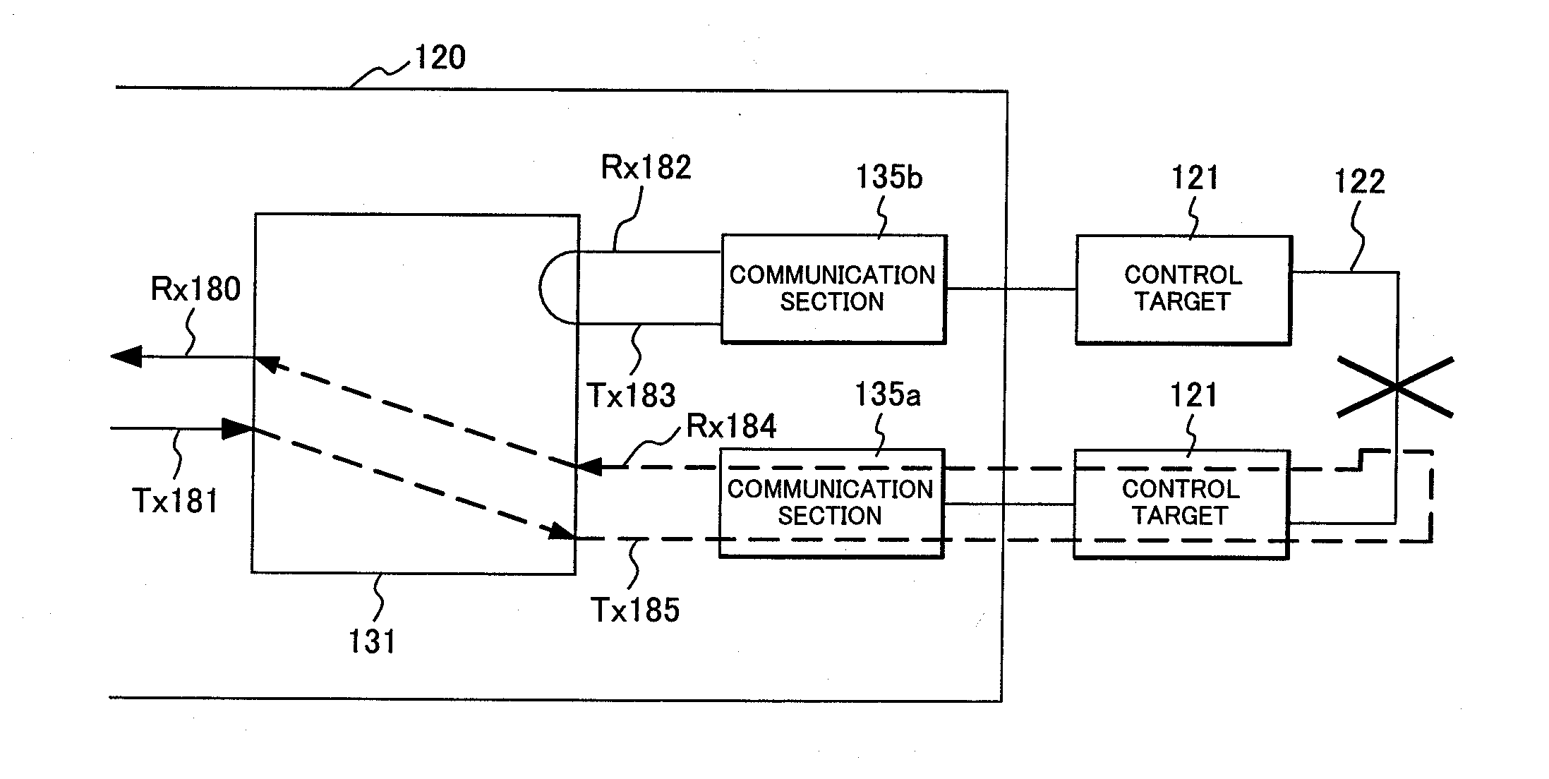
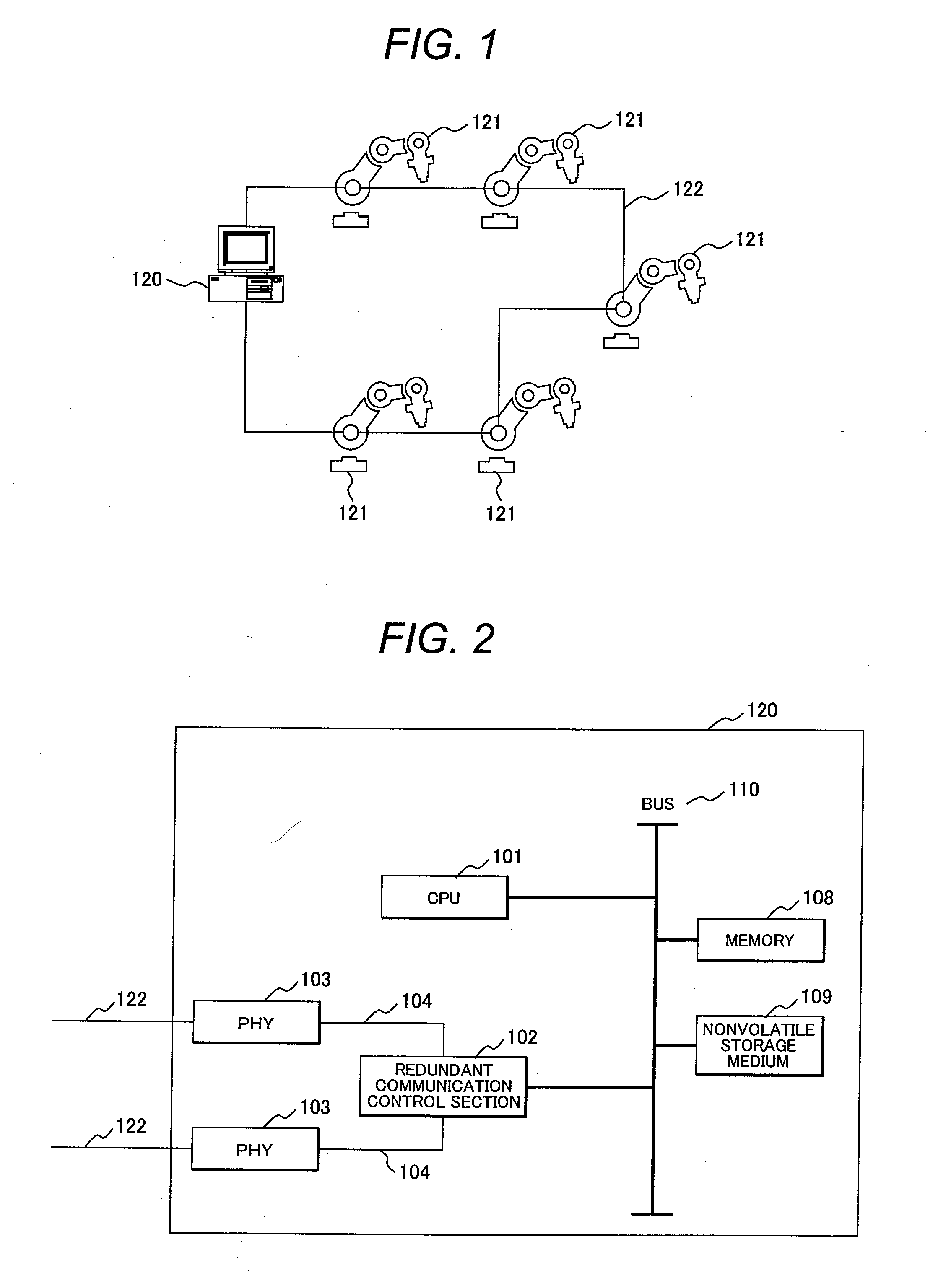
[0070]FIG. 1 is a schematic diagram showing the control network system including the information processor according to the embodiment. As shown in FIG. 1, the information processor according to the embodiment is used as a control computer (master) 120 that controls a control target (slave) 121 connected via a control network 122.

[0071]The control computer 120 includes two Ethernet communication ports for connection with the control network 122 and is connected to multiple control targets 121 via the control network 122. The control targets 121 include a servo amplifier and a servomotor. The control network 122 is equivalent to Ethernet (registered trademark). The network in FIG. 1 configures the ring topology and may also use the star topology, the line topology, or the composite topology configured by combining these topologies for the hardware configuration as long as it logically complies with the ring topology.

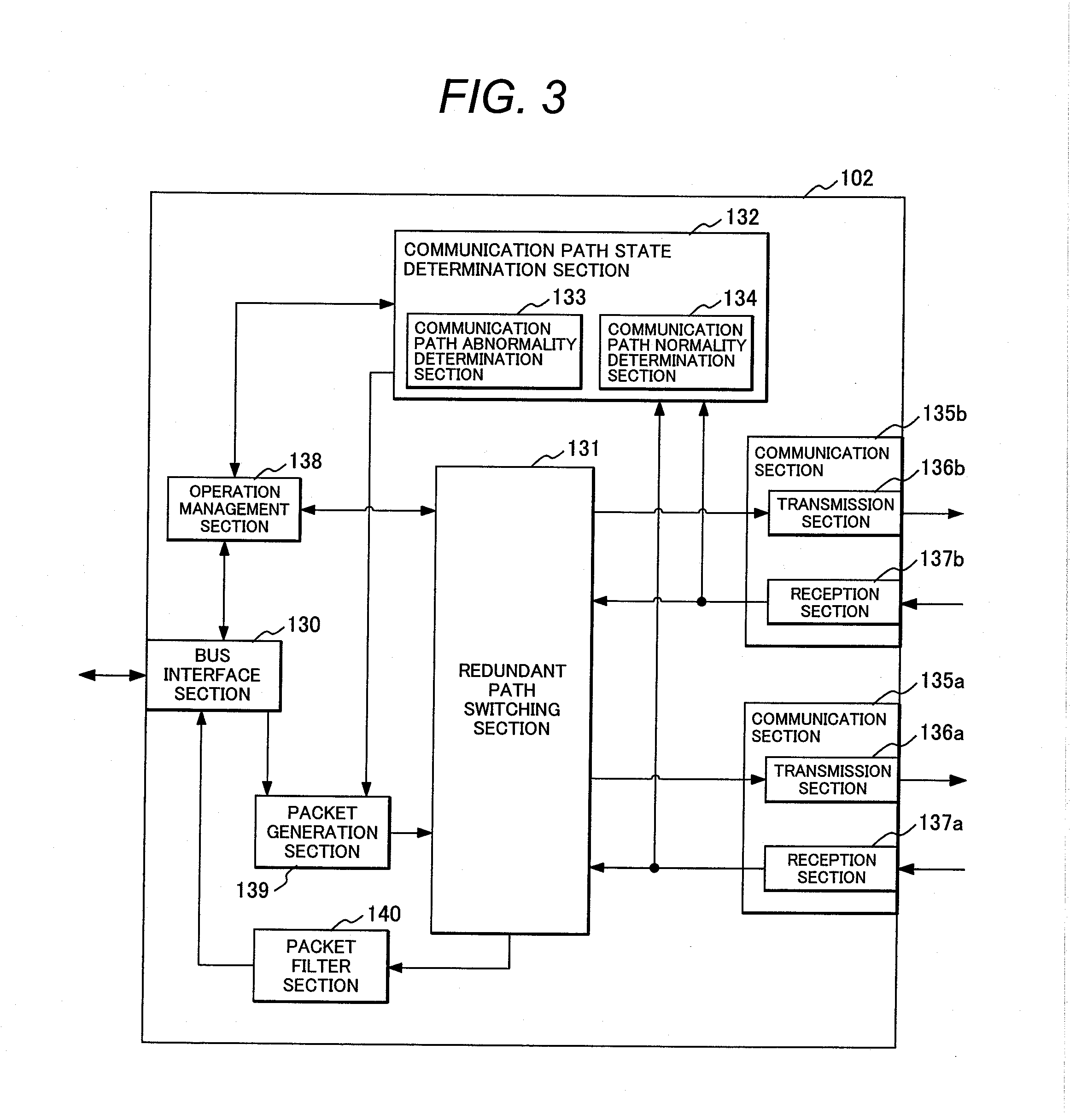
[0072]FIG. 2 is a block diagram showing the hardware configuration o...

second embodiment

[0130]The second embodiment will be described. FIG. 18 is a block diagram showing the hardware configuration of a control computer 180 according to the embodiment. FIG. 19 is a schematic diagram showing the configuration of the control network system using the control computer 180 shown in FIG. 18. As shown in FIGS. 18 and 19, the control computer 180 according to the embodiment includes four communication ports. The control computer 180 configures a control network having two ring networks 122a and 122b in each of which two communication ports are physically connected to each other.

[0131]FIG. 17 is a block diagram showing the function configuration of a redundant communication control section 181 according to the embodiment. Unless otherwise specified, the mutually corresponding components or functions in FIGS. 17 and 3 are designated by the same reference numerals. As shown in FIG. 17, the redundant communication control section 181 according to the embodiment differs from the red...

third embodiment

[0154]The third embodiment will be described. FIG. 28 exemplifies a hardware configuration of the redundant communication control section 191 provided for the control computer according to the embodiment. Unless otherwise specified, the mutually corresponding components or functions in FIGS. 28 and 3 are designated by the same reference numerals. The control computer including the redundant communication control section in FIG. 28 uses the same hardware configuration as that in FIG. 2.

[0155]As shown in FIG. 28, the redundant communication control section 191 differs from the redundant communication control section 102 in that an auto-increment address conversion section is provided in the packet generation section. An auto-increment address conversion section 141 converts an auto-increment address in a command issued to it in accordance with communication path states.

[0156]The control network system using the control computer according to the third embodiment is the same as that of ...


PUM


Abstract

An information processor capable of ensuring time synchronization accuracy, ensuring EtherCAT command consistency, and easily developing the software based on a 2-port configuration even when a communication path error occurs includes: an arithmetic section; at least two communication sections each including a transmission section and a reception section; and a redundant communication control section that controls a communication path between the arithmetic section and the communication section. The redundant communication control section includes: a communication path state determination section that determines a network path state; and a redundant path switching section that switches connection between the arithmetic section and at least two communication sections. The network provides a logical ring topology for a packet communication path. The redundant path switching section functions based on the communication path state determined by the communication path state determination section and changes a connection path between the communication sections and a communication path between the communication section and the arithmetic section.

Description

CLAIM OF PRIORITY[0001]The present application claims priority from Japanese Patent Application No. 2010-040419 filed on Feb. 25, 2010, the content of which is hereby incorporated by reference into this application.BACKGROUND OF THE INVENTION[0002]1. Field of the Invention[0003]The present invention relates to an information processor including information processing hardware and information processing software used for redundant networks for real-time communication and to a control network system including the information processor and control targets.[0004]2. Description of the Related Art[0005]In some control systems, a single control computer controls one or more control targets via a network. As a control system example, a control network system allows one control computer to be connected with multiple control targets via the ring topology. In this control network system, a control packet is transmitted from the control computer to multiple control targets in order. The control...

Claims


Application Information

Patent Timeline
Patent Type & Authority Applications(United States)
IPC IPC(8): H04L1/00
CPCH04L12/413H04L12/40176H04L12/437
Inventor MARUYAMA, TATSUYAYAMADA, TSUTOMUYANAGIHARA, NORIHISAYONEMOTO, SHINJIIWAKI, TAKASHIOHASHI, HIRONORIMATSUMOTO, YUTAKA
Owner HITACHI IND EQUIP SYST CO LTD
Why Eureka
Try Eureka